4.1 Geological Settings
Anisotropy and existing discontinuities, inherent to the various types of rock, have a strong influence on the fracture network (Figure 42). For example, bedding planes can lead to the existence of fractures limited by strata (stratabound model) with spacing and length related to thickness of the layers (Gross, 1993). On the other hand, the non-stratabound model applies to massive rocks in which there are no lithological layers confining the fractures. In this case, fractures show a wide range of sizes (distribution of their sizes are often lognormal or exponential). These fractures are vertically persistent and spatially grouped (clustered), forming fracture zones (Odling et al., 1999).
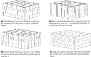
Figure 42 – Fracture network idealized models: a) stratabound, b) non-stratabound, c) hierarchical, and d) top- bounded (modified from Odling et al., 1999; Gross & Eyal, 2007; Laubach et al, 2009, in Hooker et al., 2013).
Considering the general conceptual models of the fracture networks associated with specific lithologies, rocks are herein grouped into the following geological settings: sedimentary rocks, volcanic rocks, metamorphic and igneous rocks, and fault zones.
4.1.1 Sedimentary Rocks
In the fracture systems of sedimentary rocks, the bedding-plane partings (fractures parallel to and along bedding) generally form a subhorizontal fracture set. These bedding- plane partings are frequent and usually relevant to flow (Morin et al., 1997; Michalski & Britton, 1997; Lemieux et al., 2006; Gross & Eyal, 2007; Chesnaux et al., 2009).
Intercalated lithological beds, especially when their composition and/or texture are contrasting, can control the fracturing as shown in Figure 43 (Gross, 1993; Underwood et al., 2003; Cooke et al., 2006). In those settings a large number of fractures are bed-confined, resulting in stratabound fracture networks (Odling et al., 1999). Older and persistent fractures can also control the propagation of younger fractures, and this may give rise to a pattern of older systematic joints and younger cross joints (Figure 43b, Figure 44). Cross joints may also be called non-systematic joints. Multilayer (throughgoing) fracture zones may occur in the form of large fracture corridors and are more widely spaced than the more contained and bed-confined fractures, as shown in Figure 44 (Gross & Eyal, 2007). In summary, variations, and combinations between stratabound and non-stratabound fractures are observed in sedimentary rocks, with the possibility of interchanging from one to the other (Odling et al., 1999).
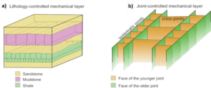
Figure 43 – Controls on fracturing in sedimentary rocks. a) Spacing and length of joints are controlled by bedding. b) Older and persistent fractures control the propagation of younger fractures, giving rise to a pattern of systematic and cross joints (modified from Gross, 1993).
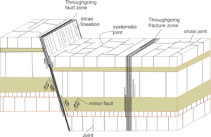
Figure 44 – Schematic of fracture hierarchy observed in layered sedimentary rocks with different bed thicknesses. Throughgoing faults and fracture zones (large-scale fracture corridors) are more widely spaced than the contained fractures that are mid-scale and bed-confined (modified from Gross & Eyal, 2007).
Bedded rocks, such as sedimentary and the very low-grade metasedimentary rocks, may be affected by curvatures and gentle folds formed at shallower crustal levels, a condition that allows the concomitant formation of fractures. These can be shear conjugates and joints organized in a predictable way with regard to the fold elements. The formed patterns vary with regard to the limbs of the fold, especially when it is asymmetric, and to its outer and inner portions particularly in thick layers. These fractures are described in textbooks such as Price & Cosgrove (1990, pages 378–379) and Ramsay & Huber (1987, page 458).
Transmissive bedding-plane fractures, usually present at shallow depths, are considered to be the major groundwater flow paths in sedimentary rocks. This and other flow characteristics of this geological setting are presented in Section 5.1 which describes conceptual groundwater flow models in sedimentary rocks developed in case studies.
4.1.2 Continental Flood Basalts
For discussion of volcanic rocks in this book we chose to deal with continental flood basalts. These represent the most remarkable examples of volcanic activity on the Earth’s surface (Bondre et al., 2004; Jerram & Widdowson, 2005). Their mean thickness ranges from 500 to 1,000 m and their volume can be of the order of 300,000 to 450,000 km3 (Tolan et al., 1989; Frank et al., 2009). The most studied continental flood basalt provinces include the Columbia River Basalt Group (age ranging from 17.5 to 6 Ma; Hooper, 1997) in the northwestern United States, and the Deccan Traps (70 to 60 Ma; Baksi, 1987) in west-central India. These continental floods mainly comprise very extensive basalt sheet-like lobes. A sheet flow is a body of very fluid basaltic lava in which new lava is continuously injected in the central portion of the flow, a phenomenon called inflation that is typical of pahoehoe flows. Emplacement on flat and low dip surfaces favors the production of sheet-like lobes with lateral extension that can reach more than 1,000 km (Self et al., 1998; Self et al., 2008).
Each solidified basalt flow bears two horizontal vesicular layers, one at the base (typically about 1 m thick) and another at the top (generally a few meters to a few tens of meters thick). Between the vesicular zones lies the central layer, from several meters to tens of meters thick, that consists of compact basalt (Figure 45) usually characterized by a dense fracture network formed from the shrinkage of the rock during the lava cooling. This network contains both horizontal and vertical joints. The latter are the most prominent as they frequently form tall vertical columns, usually several decimeters in diameter, typical of the so-called columnar basalts that form colonnade layers. The upper portions of some basalt flows are characterized by very dense joints that may be either chaotic or form thin irregular columns usually up to 10 or 20 centimeters in diameter; these features are typical of entablature basalt. One would expect that the primary porosity of these rocks (vesicles and spaces between cooling joints) would provide a significant permeability, and this is often the case for younger basalts. However, in older basalts, this porosity can be substantially reduced due to mineral infilling of the shrinkage cracks (Jalludin & Razack, 1994; Gannett et al., 2007). In basalts that have an entablature layer, subhorizontal and persistent transmissive fractures may be present at the contact between the entablature and colonnade layers, or at the lower contact of the basalt flood; these are described by Fernandes and others (2016a) in the Serra Geral basalts, Paraná Basin in Brazil (Figure 45, Figure 46, Figure 47, Figure 48, Figure 49). The authors report that these persistent fractures were generated by hydraulic fracturing due to the trapping of residual fluids caused by the rapid cooling, typical of the entablature layer. Thus, they conclude that it is useful to record the presence of an entablature when prospecting for water supply. Sediments, usually occurring as thin and discontinuous layers between successive basalt flows, are quite common and may bear significant groundwater flow. The interaction of the lava with water-saturated sediments produces peperites that usually look like breccia and consist of fragments of vesicular basalt contained in a sandstone matrix.
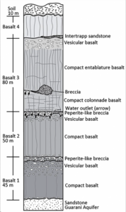
Figure 45 – Vertical sequence of sheet-like lobe basalt flows with a minimum lateral extent ranging from 100 to 200 km (Fernandes et al., 2018). Basalts 1, 2 and 3 bear the typical internal zones of a solidified flow: a thin vesicular layer at the bottom, compact and usually densely fractured (cooling joints) basalt in the middle portion, and a thicker vesicular layer at the top. Thin and laterally discontinuous intertrapp sandstones and breccias (usually at the bottom of the flow) are also common features. Peperite-like breccias are formed by the interaction between the sandstone intertrapp layers with the basaltic lava. The most transmissive fractures (water outlets shown as black arrows) in this basalt sequence are associated with hydraulic fracturing in Basalt 3 at the bottom of the colonnade layer or between the colonnade and entablature layers (modified from Fernandes and others, 2010).
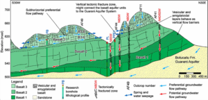
Figure 46 – Groundwater flow conceptual model of the fractured Serra Geral Aquifer System in Ribeirão Preto area, São Paulo, Brazil. The aquifer system consists of basalts of the Paraná Magmatic Province. Blue arrows show preferential flow pathways, which were identified in outcrops and boreholes (Wahnfried, 2010), as well as the flow in the underlying Botucatu Formation (Fm.) of the Guarani Aquifer System. Red arrows indicate potential groundwater flow paths along the contact between Basalt 1 vesicular layer and Basalt 2 as well as along possible subvertical fracture zones. Whether and, if so, where subvertical fracture zones cross the vesicular layers is unknown. Basalt 3 is constituted of colonnade (B3-C) and entablature (B3-E) layers. In the vesicular layers, both vertical and horizontal fractures are very sparse and discontinuous, thereby causing them to typically act as regional hydraulic barriers, i.e., aquitards (Fernandes et al., 2016a).
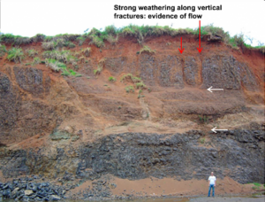
Figure 47 – Close to the surface, both vertical (red arrow) and horizontal (white arrow) fractures show intense weathering that is evidence of groundwater flow. Deeper, flow through vertical fractures becomes less and less common as flow is primarily carried to the horizontal fractures (Fernandes et al., 2011 and 2016a).
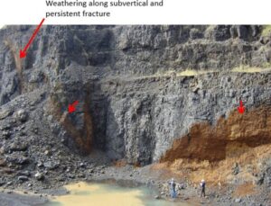
Figure 48 – Vertical tectonic fractures are deeply weathered (ocher colors) at depths of more than 40 m (the lower limit is not visible), indicating the presence of flow. The red arrows point to one persistent subvertical fracture (Fernandes et al., 2011 and 2016a).
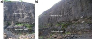
Figure 49 – In the Serra Geral Aquifer (São Paulo, Brazil), the most important groundwater flow pathways in basalt are persistent subhorizontal fractures, which usually occur at the colonnade and entablature contact, as shown in a) and b). Vegetation and water seepage along the fractures are evidence of water flow (Fernandes et al., 2011 and 2016a).
Preferential pathways for groundwater flow in basalts associated with the typical basalt layering and fracture patterns are presented in Section 5.2 which describes conceptual groundwater flow models of layered flood basalts developed from case studies. Section 5.2 also discusses the numerous dolerite dikes associated with flood basalts. The dikes act as both carriers of and barriers to groundwater flow.
4.1.3 Metamorphic and Intrusive Igneous Rocks
The fracture system configurations of massive intrusive rocks such as granite, and of metamorphic rocks, have some typical characteristics that constrain their conceptual groundwater flow models, as explained in Section 5.3 based on case studies. Due to the usual reactivation of foliation, for example, the metamorphic rocks will have a denser and more connected fracture network compared to that of massive granites, implying a usually larger amount of groundwater flow. Persistent high dip fractures and fracture zones, which increase the vertical flow and connectivity, are much more common in these hard rocks than in the sedimentary ones. Massive and foliated granites may have fracture sets that are regionally identified in other granites and metamorphic rocks. However, it is not uncommon to find unique fracture systems in granites. Therefore, defining the extent of the domain of a conceptual fracture network model requires that structural surveys be conducted in a larger number of rock exposures. In this section we briefly describe the results of some case studies that illustrate the characteristics typical of metamorphic and intrusive rocks.
Fractures parallel to and along foliation surfaces and along other types of structures, such as veins, are abundant in metamorphic and intrusive rocks (Boutt et al., 2010; Manda et al., 2008; DesRoches et al., 2014; Fernandes et al., 2016b). This is because the reactivation process requires lower stresses (as described in Section 3.4) compared to the formation of fractures transverse to existing structures. Throughgoing fractures are much more common in metamorphic rocks than in sedimentary rocks. Even low-grade metasedimentary rocks, which preserve strong stratification, can bear significant throughgoing fractures; this is the case of the meta-sandstones of the Canastra Group in Minas Gerais, Brazil (Figure 50).
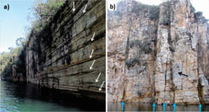
Figure 50 – Meta-sandstones of the Canastra Group, Capitólio Canyons, in Minas Gerais, Brazil. a) The outcrop vertical face is itself a throughgoing subvertical fracture that is laterally very continuous. This fracture cuts across the bedding of low-grade metamorphic sandstones. Horizontal fractures parallel to and along the bedding (white arrows) are conspicuous (photograph: Amélia Fernandes). b) Throughgoing subvertical fractures (blue arrows) cut across the bedding of low-grade metamorphic sandstones. Another subvertical fracture set (whitish faces, black arrow) is parallel to the frontal wall of the rock exposure (photograph: Amélia Fernandes).
Two high-angle throughgoing fracture sets, striking NNE and WNW, that form a well-developed non-stratabound network in folded bedrock (Figure 51a) composed of fine- grained turbidites in northwestern New Brunswick, Canada, were described by DesRoches and others (2014). The integration of borehole televiewer logging, outcrop mapping and hydraulic packer tests revealed enhanced hydraulic conductivity associated with a subset of fractures dominated by bedding-plane and high-angle fractures striking NNE, both with directions near-parallel to the current direction of the maximum principal stress. Figure 51b shows a roadcut outcrop in the Appalachian terrain of southern Québec, Canada, where fractures are parallel and along folded foliation in schist, even at the fold hinges. Foliation parallel fractures may be significant for groundwater flow, as shown in Figure 51c; this is more thoroughly discussed below.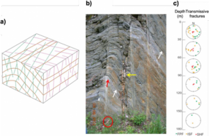
Figure 51 – Non-stratabound fracture networks in metamorphic rocks. a) Bedding parallel fracture set (brown) and two transverse high-angle throughgoing fracture sets (green and pink) forming a well-developed non- stratabound network in folded bedrock (modified from DesRoches et al., 2014). Both high-angle fracture sets seem to form conjugate shear fractures of the tectonic extensional regime. b) Example of fractures parallel and along folded schistosity (white arrows) and high dip veins (yellow arrow), which transect the foliation in the southern Québec Appalachians, Canada. The fractures accompany the foliation of schist even at the fold hinges (red arrow). For scale, the red circle highlights the position of a rock hammer (photograph: Alain Rouleau). The number of transmissive fractures in foliated crystalline rock decreases with depth (modified from Boutt et al., 2010). FPF = foliation parallel fracture. ISF = intermediate to high dip fracture. SHF = subhorizontal fracture.
In a crystalline basement quarry located in the São Paulo Metropolitan Region, Brazil rock weathering along and adjacent to fractures parallel to low dip foliation in granitic gneiss provided evidence of significant groundwater flow along the fractures (Fernandes et al., 2016b; Fiume et al., 2020). Flowmeter measurements in vertical wells, drilled through gneisses, granites, and schists, also indicate that foliation parallel fractures are the ones that mostly contribute to the production of the wells. At the studied locations, foliation is gently folded and this imposes an orientation variation on the fractures that are parallel to the foliation. Although the orientation variation observed in the data might lead a person to think that the fractures intersect to form a connected network, this is not the case because the foliation surfaces are parallel. High dip fractures can be either throughgoing or abut against part of the foliation parallel fractures, leading either to a non- stratabound or to a hierarchical fracture network in different sectors of the same rock mass (Figure 52).
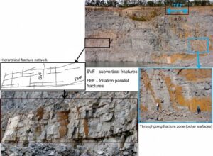
Figure 52 – The same granitic gneiss exposure shows two types of fracture networks. In the black box on the left subhorizontal fractures parallel to the gneiss foliation (FPF in the sketch) are persistent, while the subvertical fractures (SVF) are discontinuous and partially abagainst the subhorizontal fractures. This gives rise to a hierarchical fracture network. On the other hand, a throughgoing vertical fracture zone (TFZ, ocher surfaces) is present in the right portion of the upper photograph; a detail of this TFZ is shown in the blue box on the right (modified from Fernandes et al., 2016b).
Igneous and metamorphic rocks of Nashoba and Avalon terranes, located in eastern Massachusetts, ranging from massive, non-foliated intrusive rocks to foliated high-grade metamorphism rocks were investigated by Manda and others (2008) and Boutt and others (2010). These authors surveyed and analyzed fracture attributes (i.e., trace-length, spacing, termination, and orientation) to assess the influence of lithology and fabric on fracture distribution and type. The orientation of two major regional steep fractures is independent of rock type, whereas foliation-parallel fractures (FPFs) are subparallel to the axis of the terrane. Subhorizontal fractures (i.e., fractures with dip less than 25°) were described as sheeting joints and are also pervasive in the area. Trace-length and spacing distributions for steep fractures and FPFs are best described by lognormal distributions. The median trace lengths for FPFs vary as a function of the degree of foliation development, and the median fracture spacing for all FPFs is half that of all steep fractures. The wide variation of median spacings for FPFs in specific rock groups is explained by the presence of multiple units with varying degrees of penetrative fabric development. Generally metamorphic rocks have smaller fracture spacing than igneous rocks.
Analysis of groundwater flow in the three main fracture types (FPF and high and low dip fractures) was undertaken in the boreholes drilled in the Nashoba and Avalon terranes (Boutt et al., 2010). FPFs comprise approximately 39 percent of the total fractures in the terrane. Regional high dip tectonic fractures comprise 51 percent of the total fractures measured. Subhorizontal joints (dip < 25°) comprise the remaining 10 percent and play the largest role in conducting water in the shallow subsurface. Steeply dipping fractures, including the FPFs, act as the major connection for vertical flow. Only 2.7 percent of the fractures are hydraulically active and, of these, 32 percent are classified as FPF, 17 percent are subhorizontal and the remaining 51 percent are steep fractures. Most hydraulically active fractures (more than 70 percent) are in the upper 100 m, with a large percentage of those being even shallower (Figure 51c). The number of hydraulically active fractures is large in the upper 30 m with fracture sets of several orientations contributing to the flow. The hydraulically active subhorizontal joints disappear below 100 m. Fractures with dips greater than 40° appear to be supporting flow at greater depths.
Detailed fracture surveys in granitic intrusions (around 550 Ma in age), in moderate- to low-grade metamorphic rocks, were conducted in eight large quarries spread throughout the Metropolitan Region of São Paulo (Fiume, 2013; Fernandes et al., 2016b; Christofolletti, 2020). The integrated analysis of their results indicates the existence of three types of fracture patterns in the granites, as summarized below.
-
In five quarries comprised of massive granite, subvertical fracture sets generated under the strike-slip tectonic regime are dominant and correlated to regional fracture sets that affect the host metamorphic rocks. Medium dip (around 60°) and low dip (around 30°) fracture sets were generated in the Andersonian extensional and compressive regimes, respectively. The subvertical fracture set spacings are irregular (from decimeters to decameters) and the trace lengths vary from around a meter to much more than 70 m (Figure 53) with the latter being typical of very persistent fracture zones.
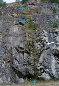
Figure 53 – Persistent (more than 70 m tall) subvertical fracture zone (blue arrows) in massive granite. The fracture zone partially abuts against medium dip fractures (white arrow) (photograph: Bruna Fiume).
- In two quarries located approximately 40 km apart, a distinct fracture network pattern exists. It consists of two sets of orthogonal fractures with the same strike but dipping in opposite senses; the dip varies from 30° to 60° and does not fit any of the Andersonian tectonic regimes. One of the sets is the product of the reactivation of quartz-feldspar veins (Figure 54). One or two regional fracture sets are also present but are less prominent. In one quarry, the granite is foliated and the quartz-feldspar veins are more abundant and parallel to the foliation. Boutt and others (2010) emphasize that foliated granites may provide the most consistent orthogonal networks of interconnected fractures. However, Wise (2005) proposed that this orthogonal pattern (called rift and grain) could be controlled by closely spaced microscopic fracture planes in quartz. These microfractures could have been produced by stresses generated during differential thermal contraction. Thermally induced grain-scale stresses, possibly augmented by weak regional stress fields, could lead to the production of systematic regional patterns during uplift (Wise, 2005).

Figure 54 – Two sets of almost orthogonal fractures with the same strike while dipping in opposite senses. One set is the product of the reactivation of quartz-feldspar veins (white arrow) and the other set (blue arrows) is perpendicular to and abuts against the first one (red arrows) (photograph: Bruna Fiume).
- The remaining surveyed granite is less than 1 km away from a large-scale east-west (EW)-trending mylonitic shear zone. This is a massive granite in which, by far, the most prominent fracture set is parallel to thin EW mylonitic shear zones and hydrothermal veins. These structures have high to medium dip and are correlated to the deformation caused by the EW-trending shear zone. This pattern again demonstrates the significance of reactivation for producing specific fracture patterns.
4.1.4 Fault Zones and Fluid Flow
Fault zones have an important impact on local and regional groundwater flow in the shallow crust (< 1 km) and, at depth, they significantly contribute to hydrocarbon migration and hydrothermal fluid circulation (Bense et al., 2013). Although these zones can constitute hydraulic conduits, the core of a fault often acts as a barrier to flow. To understand this behavior, the fault architecture, which is the focus of this section, must be characterized.
A comprehensive synthesis of permeability distribution in fault zones and flow experiments characterizing flow in four idealized types of fault architectures (Figure 55) were conducted Caine & Forster (1999). The idealized fault architectures were developed from the results of three-dimensional stochastic modeling of faults using outcrop-scale data. The data were from Stillwater Normal Fault in Dixie Valley, Nevada, USA (Caine & Forster, 1999), and a series of normal fault zones in east Greenland (Caine et al., 1996). The distribution of fault core and damage zone components in non-deforming (during tectonic quiescence) fault zones can be placed in one of four types of fault zone architectures (Figure 55). Each type has a related idealized permeability structure, that is, localized conduits (Single Fracture Fault model), distributed conduits (Distributed Conduits model), localized barriers (Localized Deformation model) and combined conduit-barriers (Combined Conduit-Barriers model). The idealized architectures represent one moment in time and space (Caine et al., 1996) and a range of styles should be expected along any single fault zone. When not actively deforming, a fault core commonly acts as a localized barrier that restricts fluid flow across the fault zone because of its reduced permeability as illustrated in Figure 55b (Caine et al., 1996; Evans et al., 1997; Gudmundsson et al., 2003).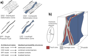
Figure 55 – Fault zone architecture styles and associated distribution of permeability. a) Idealized strike- slip faults viewed on horizontal exposures. The DDZ (distributed deformation zone) and LDZ (localized deformation zone) represent two idealized members. In SFF (single fracture fault) the deformation is accommodated along a single fault. The CDZ (composite deformation zone) is a hybrid between the DDZ and LDZ. DDZ contains networks of both open and closed macroscopic fractures that act as distributed conduits (modified from Caine et al., 1996, and Caine & Forster, 1999). b) Sketch of the distribution of fault core materials and damage zones and how the distribution relates to the overall hydraulic conductivity anisotropy (modified from Caine et al., 1996).
Rock in the fault core undergoes progressive grain-size reduction, dissolution, reaction, and mineral precipitation. This evolution typically causes the core to have reduced permeability relative to that of the adjacent damage zone and the unaffected host rock, i.e., the protolith. The host rock type has a strong influence on the structure and composition of fault cores and their permeability structure. For example, in granitic rocks the presence of feldspars may result in a fault core rich in clay minerals, and this may significantly lower permeability. Rocks with high primary permeability, such as sandstones, usually develop deformation bands. Detrital granular sequences can develop core sectors and damage zones similar to the composite deformation zone in faults that reactivated existing joints in sandstone (Aydin et al., 2006). However, the fault zone has reduced permeability compared to the primary granular permeability of the sandstone.
Damage zones adjacent to fault core components bear a network of structures such as small faults, veins, joints, and pressure solution seams. They result from the growth and linkage of fracture networks that accompany episodic deformation of the fault zone. Together these structures produce a heterogeneous and anisotropic permeability; however, the bulk damage zone permeability is greater relative to both the fault core and the protolith (Caine et al., 1996; Evans et al., 1997). Measured hydraulic conductivity (K) of fault components indicate values of K in the damage zone that are three orders of magnitude larger than that of the fault core (Evans et al., 1997). The specific characteristics of each component’s permeability depends on the in-situ stress state, rock heterogeneity, fracture interconnectivity, and the extent of fracture infilling by mineral precipitation.
In addition to the references cited in this section, we recommend reading of Bense and others (2013). It is a comprehensive paper that evaluates geological deformation mechanisms, hydrogeologic observations and conceptual models of faults in diverse rock types. We strongly recommend that structural geologists and hydrogeologists work closely together to gain a more integrated, comprehensive understanding of fault zone hydrogeology.