Box 1 Effects of Shear Displacement on the Transmissivity of a Rock Fracture
Authors: Alain Rouleau, Éric Lamontagne, Amélia João Fernandes
Shear displacement between the two faces of a rock fracture can have important impact on the flow properties of the fracture, particularly its transmissivity. This box summarizes the procedure and selected results of laboratory experiments, conducted by Lamontagne (2001), on the effects of shear on flow properties of a fracture under constant normal stress conditions. These experiments used many replicas of the same natural rock fracture.
A number of laboratory experiments have been reported in the literature over the last few decades on the effects of shear displacement on hydraulic properties of rock fractures subjected to various shear and normal stress loading conditions. The Complementary Bibliography on Shear-Flow Coupling Experiments (1990-2019) at the end of this note presents sources of information on the various laboratory equipment and methods that have been used in the experiments, the different types of specimens that have been tested, as well as the results obtained and the interpretation made by the researchers.
Box 1.1 Fabricating Replicas of a Natural Fracture
The original sample was a natural extension fracture in a granitic rock from France. The rock core containing the fracture had been collected with a 120 mm core barrel in a hole drilled perpendicular to the average fracture plane (Gentier, 1987; Flamand, 2000). A silicone negative mold was fabricated of both faces of the rock fracture. Fracture face replicas were fabricated by pouring mortar into the negative mold and letting it cure for at least 30 days. Each fracture replica was obtained by superposing the concrete-fabricated replica of both fracture faces, taking proper care to reproduce the exact relative orientation of the faces. The mechanical and hydraulic properties (hydraulic conductivity, K, of 5.1 ×10⁻¹³ m/s) of the replica material were considered adequate to simulate the original granitic rock. The mechanical properties of many fracture replicas have been characterized by careful testing systematically conducted under a wide variety of normal and shear stress conditions (Flamand et al., 1994; Flamand, 2000); the fabricated fractures have shown mechanical characteristics similar to those of a natural fracture in granite.
The morphology of the fracture was almost identical from one replica to the other. The upper and bottom surfaces of the same fracture replica shown in Figure Box1-1 illustrate how the two faces formed a well-imbricated fracture surface. An orientation marker was placed at the same location on both faces of every replica (Figure Box1-1) to determine the sense of shear to be applied in the testing machine.
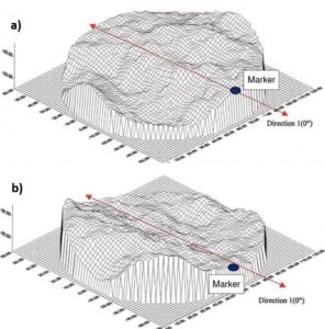
Figure Box 1-1 – Replicated fracture. a) Reconstructed upper wall and b) bottom wall of a fracture replica before testing, showing the position the orientation marker; vertical exaggeration 10x (Lamontagne, 2001).
Box 1.2 Test Equipment and Procedure
For the replicas to be subjected to hydromechanical tests, a 6 mm diameter hole was drilled in the center of the bottom wall to be used for water injection during testing. Each fracture replica was constructed by superposing the concrete-fabricated walls of both fracture faces, each one in its own stainless-steel case placed one on top of the other (Figure Box1-2), thereby ensuring the exact relative orientation of the original fracture faces. The space separating the two cases permitted the installation of a water collecting system over the entire periphery of the tested fracture, the outflow being controlled by a thick sealing latex coat and a total of 16 drain tubes. The flexibility of the water collection system allowed a shear displacement of up to 5 mm along the fracture plane without significant water leakage outside of the controlled drainage system. The outflow was collected in eight receptacles distributed around the tested fracture, each one fed by two of the draining tubes (Figure Box 1-3) and resting on an individual weighing apparatus. This design allowed a continuous measurement of flow rate in each one of eight pie-shaped sectors constituting the entire fracture surface.
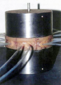
Figure Box 1-2 – A fracture replica in its two steel casings, ready for installation in the shear test machine (Lamontagne, 2001).
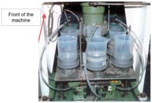
Figure Box 1-3 – The system of eight collection receptacles around the testing cell (Lamontagne, 2001).
The fracture replica and its two rock walls, the hanging wall, and the footwall, each one in a steel casing, were placed in the shear testing machine (Figure Box1-4). This is shown on the extreme right of the photograph of the laboratory setup for hydromechanical testing (Figure Box1-5).
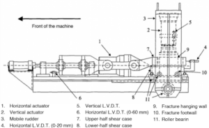
Figure Box 1-4 – Shear machine.
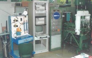
Figure Box 1-5 – Laboratory setup for hydromechanical shear testing (Lamontagne, 2001).
Each fracture replica was subjected to a single test with a constant value of normal stress and to shear displacement in one of four directions (0o, 90o, 180o and 270o). The value of normal stress and the shear direction varied from one fracture replica to the other. Water was injected at a constant flow rate through the central hole, producing diverging flow in the fracture plane. The normal stress values that were applied were 3, 5, 7 and 9 MPa. During each test, the same value of shear strain rate, 0.5 mm/min, was applied. At a number (between 4 and 13) of predetermined values of shear displacement (between 0.1 to 5.0 mm), shearing was stopped. Water was then injected at constant flow rates, between 2 and 6 different values, through the central hole in the fracture plane. The quantity of water collected in the eight receptacles, combined with the measured water pressure, was used to estimate the fracture transmissivity T and to assess the potential anisotropy of flow in the fracture plane.
Box 1.3 Selected Results
Figure Box1-6 presents the variation of the intrinsic transmissivity tf (cm3) as a function of the shear displacement based on the results of 16 tests using as many fracture replicas as possible and grouped by the value of applied normal stress (σn), which ranged from 3 to 9 MPa.
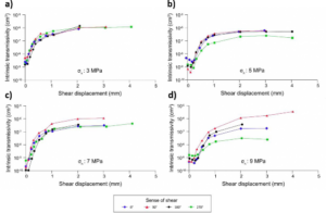
Figure Box 1-6 – Intrinsic transmissivity variation with shear displacement grouped by normal stress value: a) 3 MPa, b) 5 MPa, c) 7 MPa and d) 9 MPa (Lamontagne, 2001). Some of the graphs, particularly (b) and (d), indicate a small decrease in transmissivity (tf) for short displacements, up to about 0.5 mm, but all of the graphs show a considerable increase thereafter. Shear failure corresponding to the peak shear strength (not shown here) occurred at displacement values varying between 0.3 and 0.7 mm from one test to the other. A significant increase in tf occurred before failure. Overall, the value of tf increased by at least one, and up to more than three, orders of magnitude for all values of normal stress considered in these experiments.
The parameter tf is derived from the Navier–Stokes equation describing the flow of a viscous fluid in an open conduit. In this case, the assumed conduit is an open fracture formed by two smooth parallel walls. Let us make a comparison with Darcy’s law in a porous medium, as shown in Equation Box1-1.
|
v = –KΔh [LT-1] |
(Box1-1) |
where:
|
v |
= |
Darcy flux |
|
K |
= |
hydraulic conductivity of the medium [LT-1] |
|
Δh |
= |
hydraulic head gradient (dimensionless) |
Similarly, the hydraulic conductivity of a fracture with smooth, parallel walls is expressed as shown in Equation Box1-2.
|
𝐾𝑓 = 𝜌𝑔 𝑒2 |
(Box1-2) |
where:
|
Kf |
= |
fracture hydraulic conductivity [LT−1] |
|
e |
= |
fracture aperture [L] |
|
ρ |
= |
fluid density [ML−3] |
|
μ |
= |
fluid viscosity [ML−1T−1] |
|
g |
= |
gravitational acceleration [LT−2] |
The transmissivity of a porous aquifer of thickness B is defined as T = KB [L2/T]. Similarly, for a fracture with an aperture of e, the thickness B=e, so its transmissivity is shown in Equation Box 1-3 (Gentier, 1987).
|
𝑇f = 𝐾f 𝑒 = 𝜌𝑔 𝑒2 𝑒 = 𝜌𝑔 𝑒3 [L2/T] (Box 1-3) |
Intrinsic parameters are also defined for a fracture as they are for a porous medium. The intrinsic parameters are independent of the fluid properties, such as its density and viscosity, and they are valid for any flowing fluid either a gas or a liquid. We know that the intrinsic permeability of a porous medium (K) is defined by K = K(μ/ρg). Then, from Equation Box1-2 we can write Equation Box1-4.
|
𝑘 = 𝐾f 𝜇 = 𝑒2 [L2] |
(Box1-4) |
The intrinsic transmissivity of a fracture is then defined by Equation Box1-5.
|
t𝑓 = 𝐾f e = 𝜌𝑔 𝑒2e = 𝜌𝑔 𝑒3 |
(Box 1-5) |
Another result of these tests concerns the preferential flow direction and its variation during shear (Gentier et al., 1997). Figure Box1-7 indicates that flow tends to be higher in the direction perpendicular to shear and that this flow anisotropy generally becomes more pronounced with increasing flow rate.
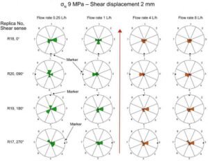
Figure Box 1-7 – Volume percentage of water collected from each of the eight sectors of the fracture plane for the four tests conducted at σn = 9 MPa on four different fracture replicas, R17 to R20. At a shear displacement of 2 mm, four water injection tests were conducted at 0.25, 1.0, 4.0 and 8.0 L/h. The red arrow indicates the sense of displacement of the upper fracture face, the lower face being immobile. The scale varies from 0 to 100% on each radius. The location of the orientation marker shows the fracture plane orientation in the shear testing machine, which varied by 90o from one test to the other. The results show that flow tends to be higher in the direction perpendicular to shear and that this anisotropy generally becomes more pronounced with increasing flow rate (Lamontagne, 2001).
Box 1.4 Applications to Field Conditions
The experiments described thus far in this section are called shear-flow coupling tests. Interpretations of the results of these tests are summarized in this section. Further information about shear-flow coupling experiments conducted by other researchers is summarized in the references cited in Section Box 1.7 Complementary Bibliography on Shear-Flow Coupling Experiments (1990-2019).
Any fracture in rock bears asperities that are more or less matching between its two faces. When a fracture is subjected to shear stress, shear displacement takes place not only along the general fracture plane, but also along asperity surfaces that are oriented at some angle (angle i in Figure Box1-8a) with respect to the general fracture plane. Sliding along the slope of asperities induces a displacement component that is normal to the fracture plane, commonly called “shear dilation” (Figure Box1-8b). The resulting fracture opening significantly increases the fluid flow properties of the fracture.
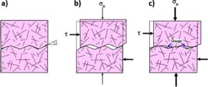
Figure Box 1-8 – Effects of shear displacement on fracture aperture. a) The asperities on fracture faces are relatively well matched before shear displacement, with little void space for water flow. b) Shear stress (τ) is applied under low normal stress (σn) conditions; the resulting shear displacement includes a component normal to the fracture plane (shear dilation) due to local shear along asperity slopes oriented at an angle i with respect to the fracture plane. c) At higher normal stress the shear dilation is constrained and the asperities tend to be crushed by the displacement parallel to the fracture plane, generating fine-grained material (gouge) that partly fills the void space (after T. Doe, personal communication, 2020).
Many experiments have demonstrated that this shear dilation decreases with increasing normal stress applied to a fracture during the shear test. This decrease in dilation is considered to be the result of a higher proportion of asperities being crushed during the test at higher normal stress (Figure Box1-8c). Moreover, asperity crushing generates fine grained material (gouge) that fills parts of the voids and may hamper fluid flow along the fracture plane. The process of shear dilation increases fracture transmissivity; conversely, the processes of asperity crushing and infilling of voids by gouge material tend to decrease transmissivity. All of these processes are likely to take place in all fractures subjected to shear, and their relative importance varies depending on a number of factors, including the normal stress, rock type and amount of shear displacement. A detailed field study describing the generated features at a specific site will help to determine the effects of shear on transmissivity of that site.
The depth range relevant to many fractured aquifer applications extends to around 350 m, and most of the laboratory experiments indicate that shear dilation is the predominant process taking place at those depths. In the depth range between 100 to approximately 350 m, the vertical stress values vary from 3 MPa up to 9 MPa, estimated using the relationship σv = ρgz, where ρ is the average rock density, g is the gravitational acceleration and z is depth. Considering a horizontal fracture, the normal stress is equal to the vertical stress. At normal stresses of 3 MPa to 9 MPa, the laboratory tests in general show an increase in the fracture transmissivity due to shear displacement (Figure Box1-6).
These results are applicable to the flow properties of fractured rock at a wide variety of scales. Field observations at a regional scale have been reported where higher transmissivity values are obtained for fractures that are critically oriented for shear displacement due to in-situ stress conditions (Barton et al., 1995; Ferril et al., 1999). Sedimentary rock units often experience some shear, particularly for fractures along bedding planes, even under minimal gentle folding. These conditions are commonly observed in sedimentary rock basins; an example is described by Morin and others (2007) in the St. Lawrence Lowlands in southern Québec, Canada.
At a local scale, shear along fracture planes is likely induced in existing fracture systems around underground excavations such as tunnels and mining stopes. Indeed, the presence of an excavation results in variations in the in-situ stress tensor, both in magnitude and in orientation, in the host rock mass. These variations are significant up to a radial distance of about twice the diameter of the excavation. Figure Box1-9a shows the orientation of the major (σo) and the minor (σ3) principal stresses, as well as the increase in magnitude of σo (σo′ – σo) due to the presence of the excavation. These stress tensor variations are translated into changes in normal stress (σn) and shear stress (τ) conditions along every fracture plane that is present in the disturbed zone (Figure Box1-9b). The variation in shear stress along a fracture plane is likely inducing displacement along that plane, which, in turn, could result in a significant increase in the transmissivity of the fracture, at least locally. Considering this effect could be useful in gaining a more accurate estimation of groundwater flow into an underground excavation.
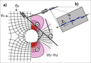
Figure Box1-9 – a) Schematic illustration of stress around an excavation in a homogeneous elastic medium; σo and σ3 are initial conditions of the major (horizontal) and minor principal stresses; σo/σ3=2; σo’ is the major principal stress in the presence of the excavation. The stress field is symmetric so the right side of the image is used to illustrate σo’– σo which is the change in stress caused by the excavation. There is an important increase in the major principal stress at the ceiling and at the floor of the excavation, and a substantial decrease at the wall (modified after Hoek & Brown, 1980b, page 492). b) Normal stress (σn) and shear stress (τ) on a fracture plane.
Let us now consider the scale of a borehole in hard rock. A borehole is a small diameter vertical tunnel that introduces a stress disturbance which changes stress components in existing fracture planes extending to a radial distance corresponding to a few times the hole diameter. The resulting shear displacement along fracture planes around the borehole could affect the transmissivity of the fractures. This effect may impact the capacity of a borehole to yield water from a fractured aquifer.
Box 1.5 Wrap-up
Shear is an essential component in the formation and propagation of both shear and hybrid fractures. The results of laboratory experiments presented in this section show that shear along an existing fracture plane may considerably increase the transmissivity of a fracture. These conclusions underscore the importance of conducting careful structural geologic surveys in the hydrogeological characterization of fractured aquifers. Evidence of shear displacement in the reactivation of a fracture plane, mainly under the current stress field, may constitute a sound indication that a fracture has hydrogeological importance.
Indeed, the possible or even likely tendency for the shear to increase transmissivity may have also caused a flow anisotropy within the fracture plane. Furthermore, knowledge about the present in-situ stress magnitude and orientation, combined with data regarding the fracture system, can permit identification of fractures that are critically oriented for a possible reactivation by shear under the present conditions. That reactivation by shear may also produce further fracture propagation thus greater spatial extent of fractures, possibly resulting in a more connected fracture network.
Box 1.6 References
Barton, C.A., M.D. Zoback, & D. Moos, 1995, Fluid flow along potentially active faults in crystalline rock. Geology, volume 23, issue 8, pages 683-686, doi: 10.1130/0091-7613(1995)023%3C0683:FFAPAF%3E2.3.CO;2.
Ferrill, D.A., J. Winterle, G. Wittmeyer, D. Sims, S. Colton, A. Armstrong, & A.P. Morris, 1999, Stressed rock strains groundwater at Yucca Mountain, Nevada. GSA Today, Geological Society of America, volume 9, issue 5, pages 1-8, Link to GSA Today article.
Flamand, R., 2000, Validation of a mechanical behavior model for rock shear fractures. Doctor of Philosophy Dissertation, University of Québec at Chicoutimi, Canada, 379 pages, Link to Dissertation (in French).
Flamand, R., G. Archambault, S. Gentier, J. Riss, & A. Rouleau, 1994, An experimental study of the shear behavior of irregular joints based on angularities and progressive degradation of the surfaces. 47th Canadian Geotechnical Conference, Halifax, Nova Scotia, Canada, pages 253-263.
Gentier, S., 1987, Morphology and hydromechanical behavior of a fracture in a granite under normal stress: experimental and theoretical study. Bureau of Geological and Mining Research, Orléans, France, number 134, 597 pages, Link to Thesis (in French).
Gentier, S., E. Lamontagne, G. Archambault, & J. Riss, 1997, Anisotropy of flow in a fracture undergoing shear and its relationship to the direction of shearing and injection pressure. International Journal of Rock Mechanics and Mining Sciences, volume 34, issues 3-4, 12 pages, doi: 10.1016/S1365-1609(97)00085-3.
Hoek, E. & E.T. Brown, 1980b, Underground Excavations in Rock. The Institution of Mining and Metallurgy, London, United Kingdom, 527 pages.
Lamontagne, E., 2001, Hydromechanical study of a shear fracture under constant normal stress. Doctor of Philosophy Dissertation, University of Québec at Chicoutimi, Canada, 484 pages, Link to Dissertation (in French).
Morin, R., R. Godin, M. Nastev, & A. Rouleau, 2007, Hydrogeologic controls imposed by mechanical stratigraphy in layered rocks of the Chateauguay River Basin, a U.S.-Canada transborder aquifer. Journal of Geophysical Research, volume 112, issue B4, doi: org/10.1029/2006JB004485.
Box 1.7 Complementary Bibliography on Shear-Flow Coupling Experiments (1990- 2019)
Auradou, H., G. Drazer, J.P. Hulin, & J. Koplik, 2005, Permeability anisotropy induced by the shear displacement of rough fracture walls. Water Resources Research, volume 41, issue 9, doi: 10.1029/2005WR003938.
Esaki, T., S. Du, Y. Mitani, K. Ikusada, & L. Jing, 1999, Development of a shear-flow test apparatus and determination of coupled properties for a single rock joint. International Journal of Rock Mechanics and Mining Sciences and Geomechanics Abstracts, volume 36, issue 5, pages 641-650.
Gale, J.E., R. MacLeod, & P. LeMessurier, 1990, Site characterization and validation— measurement of flowrate, solute velocities and aperture-variation in natural fractures as a function of normal and shear stress, stage 3. Stripa Project Technical Report, volume 90, issue 11, 96 pages, PDF.
Hans, J. & M. Boulon, 2003, A new device for investigating the hydro-mechanical properties of rock joints. International Journal for Numerical Analytical Methods in Geomechanics, volume 27, issue 6, pages 513-548, doi: 10.1002/nag.285.
Javadi, M., M. Sharifzadeh, K. Shahriar, & Y. Mitani, 2014, Critical Reynolds number for nonlinear flow through rough-walled fractures: the role of shear processes. Water Resources Research, volume 50, issue 2, pages 1789-1804, doi: 10.1002/2013WR014610.
Lee, H.S. & T.F. Cho, 2002, Hydraulic characteristics of rough fractures in linear flow under normal and shear load. Rock Mechanics Rock Engineering, volume 35, issue 4, pages 299-318, doi: 10.1007/s00603-002-0028-y.
Li, B., Y. Jiang, T. Koyama, L. Jing, & Y. Tanabashi, 2008, Experimental study on hydromechanical behavior of rock joints by using parallel-plates model containing contact area and artificial fractures. International Journal of Rock Mechanics and Mining Sciences, volume 45, issue 3, pages 362-375, doi.org/10.1016/j.ijrmms.2007.06.004.
Matsuki, K., Y. Kimura, K. Sakaguchi, A. Kizaki, & A.A. Giwelli, 2010, Effect of shear displacement on the hydraulic conductivity of a fracture. International Journal of Rock Mechanics and Mining Sciences, volume 47, issue 3, pages 436-449, doi.org/10.1016/j.ijrmms.2009.10.002.
olsson, R. & N. Barton, 2001, An improved model for hydromechanical coupling during shearing of rock joints. International Journal of Rock Mechanics and Mining Sciences, volume 38, issue 3, pages 317-329, doi: 10.1016/S1365-1609(00)00079-4.
olsson, W.A. & S.R. Brown, 1993, Hydromechanical response of a fracture undergoing compression and shear. International Journal of Rock Mechanics and Mining Sciences & Geomechanics Abstracts, volume 30, issue 7, pages 845-851, doi: 10.1016/S1365- 1609(00)00079-4.
Rong, G., J. Yang, L. Cheng, & C.B. Zhou, 2016, Laboratory investigation of nonlinear flow characteristics in rough fractures during shear process. Journal of Hydrology, volume 541, part B, pages 1385-1394, doi: 10.1016/S1365-1609(00)00079-4.
Wang, C., Y. Jiang, H. Luan, J. Liu, & S. Sugimoto, 2019, Experimental study on the shear- flow coupled behavior of tension fractures under constant normal stiffness boundary conditions. Processes, volume 7, issue 2, 57 pages, doi: 10.3390/pr7020057.
Xiong, X.B., B. Li, Y.J. Jiang, T. Koyama, & C.H. Zhang, 2011, Experimental and numerical study of the geometrical and hydraulic characteristics of a single rock fracture during shear. International Journal of Rock Mechanics and Mining Sciences, volume 48, issue 8, pages 1292-1302, doi: 10.1016/j.ijrmms.2011.09.009.
Yeo, I.W., M.H. de Freitas, & R.W. Zimmerman, 1998, Effect of shear displacement on the aperture and permeability of a rock fracture. International Journal of Rock Mechanics and Mining Sciences, volume 35, issue 8, pages 1051-1070, doi: 10.1016/S0148- 9062(98)00165-X.
Yin, Q., G.W. Ma, H.W. Jing, H. Su, Y. Wang, & R.C. Liu, 2017, Hydraulic properties of 3D rough-walled fractures during shearing: an experimental study. Journal of Hydrology, volume 555, pages 169-184, doi: 10.1016/j.jhydrol.2017.10.019.