Solution Exercise 6
a) Mohr circle number 1 intercepts the shear failure envelope. Thus, under this stress condition, shear fractures will be formed. The image below shows drawings of the faults that are formed under the stress conditions represented in the Mohr diagram and table to their right. The Mohr circle shows only the stress magnitude and, in this case, is related to the formation of shear fractures (faults); the fault orientation (strike and dip) depends on the tectonic regime and on the stress orientation as specified in the table.
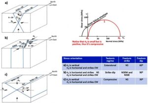
- When σ1 is vertical, the tectonic regime is extensional and normal faults are formed. The normal faults must be perpendicular to σ3 and, consequently, they strike NS. As with all of the shear fractures, the faults make an angle of ~30o with σ1 and form a conjugate pair of faults dipping ~60o, toward either E or W as shown in part (a) of the above image.
- When both σ1 and σ3 are horizontal, σ2 is vertical and the tectonic regime is strike-slip, i.e., strike-slip faults are formed. As is the case with all of the shear fractures, the faults make an angle of ~30o with σ1, which is horizontal and strikes NS. Therefore, the directions of the conjugate strike-slip faults are N30W and N30E and they are approximately vertical (dip ~90o) as shown in part (b) of the above image.
- When σ3 is vertical, the tectonic regime is compressive and thrust faults are formed. The direction of the thrust faults is perpendicular to the direction of σ1 and the corresponding normal faults strike NS. As with all of the shear fractures, they form a conjugate pair, each making an angle of ~30o with σ1; their dip is ~30o, toward either E or W as shown in part (c) of the above image.
b) Mohr circle number 2 intercepts the failure envelope at point T (i.e., it means that σ3 = T); thus, extension fractures (joints) will be formed. The image below shows drawings of the joints that are formed under the stress condition represented in the Mohr diagram and table shown below the drawings. The Mohr circle shows only the stress magnitude that, in this case, is related to the formation of extension fractures (joints). The joint orientation (strike and dip) depends on the tectonic regime and on the stress orientation as specified in the table.
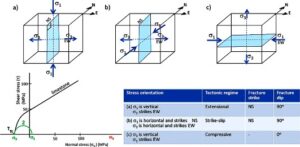
- When σ1 is vertical, the tectonic regime is extensional. Joints are perpendicular to σ3 (which is horizontal and strikes EW). Therefore, they are vertical and strike NS as shown in part (a) of the above image.
- When σ2 is vertical, the tectonic regime is strike-slip. Joints are perpendicular to σ3 (which is horizontal and strikes EW). Thus, they are vertical and strike NS as shown in part (b) of the above image.
- When σ3 is vertical, the tectonic regime is compressive. Joints are perpendicular to σ3 and, consequently, are horizontal as shown in part (c) of the above image. The existence of a vertical and negative (tensile) σ3 is possible when fluid pressure is present; this is usually possible at some depth. When horizontal fractures are formed close to the ground surface (down to ~100 m depth), they are usually sheeting joints as explained in Section 3.6.
In both extensional and strike-slip regimes, joints are vertical. One can distinguish between the two regimes when plumes are present on the joint surface. The axis of the plume is parallel to σ1 (as shown in Figure 33 and in the image presented in the solution of Exercise 8). Consequently, when the plume axis is horizontal, the tectonic regime is of the strike-slip type and when the axis is vertical, the regime is extensional (examples are shown in the photographs of Exercises 8, 9 and 11).