3.1 Stress Orientation, Tectonic Regimes and Geometric Patterns of Faults and Joints
The main objective of fractured aquifer research is determining the magnitude and the anisotropy of fluid flow within the rock. The former mostly depends on the aperture, density, orientation, and connectivity of the fractures. Fractures are generally grouped into sets having similar orientations (strike and dip) and appearing as clusters in a stereogram (as shown in the stereographic projection). The anisotropy of the hydraulic properties of the rock mass is mostly controlled by the orientations of the fracture sets, the variability of aperture (because it controls transmissivity) between the sets, and the configuration of fracture connections.
Fracture size and density are related to the brittleness of the rock, as well as to the intensity and duration of the deformation. The strike and dip of the fractures, in turn, are essentially a consequence of the stress orientation. Parallel to the Earth’s surface, shear stresses are null, causing one of the principal stresses to be vertical and the other two to be horizontal (Anderson, 1951), as shown in Figure 13. Therefore, at shallow depths where brittle deformation takes place (generally above 10 km) at any given location one of the three tectonic regimes are dominant—namely extensional, strike-slip, and compressive— in which the vertical stresses are σ1, σ2 and σ3, respectively. These are called Andersonian tectonic regimes. The names compressive and extensional are related to the type of deformation they cause in the crust. The compressive regime causes shortening and the extensional, stretching. In the strike-slip regime, neither shortening nor extension takes place. However, as discussed in this section, all the principal stresses, in each of the three regimes, can be compressive (positive) and this condition gives rise to faults. By the same token, for all of them, when σ3 is tensile (negative), joints may be formed. Each of the three regimes cause fracture direction and dip to be systematically organized. These three tectonic regimes give rise to the three classic types of faults: normal, thrust and strike-slip.
In the extensional tectonic regime, σ1 is vertical and, consequently, σ2 and σ3 are horizontal. The resulting faults dip at about 60° and the offset is mostly vertical, thereby giving rise to slickensides with striae lineation parallel to the fracture dip. These are called normal faults (Figure 21, Figure 22, and Figure 23).
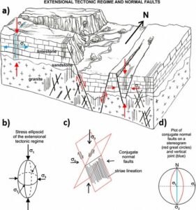
Figure 21- Extensional tectonic regime and normal faults. a) Landscape associated with areas where normal faults of the extensional tectonic regime have been recently active or are presently active, otherwise the relief once created by the fault movement would have been suppressed by erosion. Faults and joints can be formed under the same tectonic regime because the magnitude of the principal stresses can vary over time. Conjugate shear fractures are formed under compressive (positive) σ1 and σ3 (red arrows). Joints, or openingmode fractures, are formed perpendicular to a tensile (negative) σ3 (blue arrows). The joints form a set of parallel vertical fractures (the blue line is one of them). b) In the stress ellipsoid of the extensional tectonic regime, σ1 is vertical and σ3 is horizontal. c) The conjugate normal faults have the same strike (parallel traces on the terrain surface) and opposite dips (in this case, toward the west or toward the east) around 60°. The parallel lines on the fault surface represent the striae lineation parallel to the dip of the fault. d) Stereographic projection of north–south striking normal faults along with the orientation of the principal stresses.
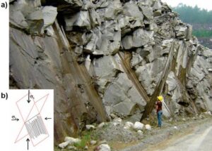
Figure 22 – Extensional tectonic regime and normal faults. a) Conjugate normal faults (Fiume, 2013) cutting through a massive granite. The outcrop is in a quarry in the São Paulo Metropolitan Region. Inset b) shows a schematic of the conjugate normal faults.
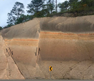
Figure 23 – Conjugate normal faults in an extensional tectonic regime (Fiume, 2013) displacing sedimentary rock beds, mostly sandstones. The shear sense is shown by the arrows. (photograph: Ricardo Hirata, nearby Tegucigalpa, Honduras).
In the compressive tectonic regime, σ3 is vertical and, consequently, σ1 and σ2 are horizontal; the faults dip at around 30° and the offset is mostly vertical, thereby giving rise to slickensides with striae lineation parallel to the fault dip. These are called thrust faults (Figure 24, Figure 25, and Figure 26).
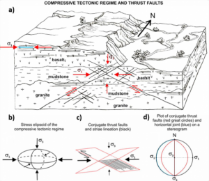
Figure 24 – Compressive tectonic regime and thrust faults. a) Landscape associated with areas where thrust faults of the compressive tectonic regime were recently or are presently active, otherwise the relief created by the fault movement would have been smoothed by erosion. Faults and joints can be formed under the same tectonic regime because the magnitude of the principal stresses may vary over time. Conjugate shear fractures are formed under compressive (positive) σ1 and σ3 (red full arrows). Relative movement is indicated by red half-arrows. Joints, or opening mode fractures, are formed perpendicular to σ3 and are horizontal (the blue line is one of them). b) In the stress ellipsoid of the compressive tectonic regime, σ1 is horizontal and σ3 is vertical. c) The conjugate thrust faults have the same strike (parallel traces on the terrain surface) and opposite dips (in this case, toward the west or toward the east) of around 30°; the parallel lines on the fault surface represent the striae lineation parallel to the dip of the fault. d) Stereographic projection of north-south striking normal faults, also showing the orientation of the principal stresses.
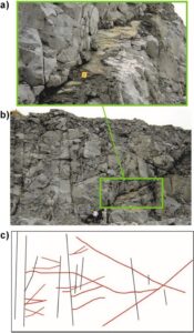
Figure 25 – Compressive tectonic regime thrust faults. a) Expanded area of green rectangular area focused on a thrust fault as shown in b). c) Schematic of (b) showing thrust faults abutting against high dip fractures (photographs: Fiume, 2013).
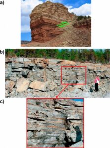
Figure 26 – Compressive tectonic regime thrust faults. a) Thrust fault (photograph: Haakon Fossen, 2016). b) Closely spaced and persistent sheeting joints that appear just below the ground surface, that are formed under a horizontal maximum principal stress (σ1) of a compressive tectonic regime, as discussed further in Section 3.6. c) Expanded view of red area in b) showing a closeup of the sheeting joints (photographs: Alain Rouleau).
In the strike-slip regime, σ2 is vertical and, consequently, σ1 and σ3 are horizontal; the faults dip close to 90° and the offset is mostly horizontal, thereby giving rise to slickensides with striae lineation parallel to the direction of the fault. These are called strike-slip faults (Figure 27, Figure 28, and Figure 29). The horizontal relative movement of the blocks separated by a strike-slip fault can be either sinistral or dextral. The fault is sinistral (left- handed) when the block that is to the left moves toward the observer (Figure 2), and the fault is dextral (right-handed) when the block that is to the right moves toward the observer. In a strike-slip fault zone, the conjugate faults are called Riedel shears, R1 and R2 (Figure 28a). R1 shear movement is consistent with the general sense of movement of the fault zone, and for R2 the sense of movement is the opposite (Figure 2a). Overlapping strike-slip faults may give rise to sectors where shortening (reduction in length) and extension (increase in length) take place across the zones simultaneously with respect to the horizontal displacements (Figure 29b,c); secondary thrust or normal faults, restricted to those sectors, may develop in association with the strike-slip faults (Ramsay & Hubber, 1987; Woodcock & Schubert, 1994, among many others). These sectors may have implications for groundwater flow, as discussed in Section 3.2 where the influence of the tectonic regime on the connectivity of, and flow within, the fracture network is discussed.
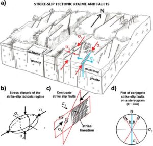
Figure 27 – Strike-slip tectonic regime and faults. a) Landscape associated with areas where strike- slip faults of the strike-slip tectonic regime were recently or are presently active, otherwise the relief created by the fault movement would have been smoothed by erosion. Faults and joints can be formed under the same tectonic regime because the magnitude of the principal stresses can vary over time. Conjugate shear fractures are formed under compressive (positive) σ1 and σ3 (red arrows). Joints, oropening mode fractures, are formed perpendicularly to a tensile (negative) σ3 (blue arrows). The joints form a set of parallel vertical fractures (indicated by the blue line). b) In the stress ellipsoid of the strike- slip tectonic regime, σ1 and σ3 are horizontal. c) The directions of the conjugate strike-slip faults make an angle of around 60° with each other (the fault traces on the terrain surface have the same pattern) and the dips are vertical. c) The parallel lines on the fault surface represent the striae lineation parallel to the strike of the fault. d) Stereographic projection of approximately N30E- and N30W-striking conjugate faults in the strike-slip regime, and the orientation of the principal stresses.
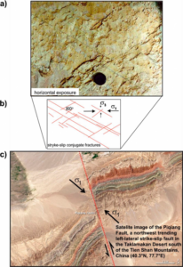
Figure 28 – Strike-slip tectonic regime shear fractures and faults. a) Horizontal exposure of a silty sandstone with fine traces of subvertical conjugate shear fractures, also called Riedel shears, as shown in the sketch b) below the photograph (Campinas, São Paulo State, Fernandes & Amaral, 2002). c) Spectacular sinistral strike-slip fault with roughly 4 km of horizontal displacement; the orientation of σ1 is approximate (Pingyiang Fault, China, https://earthobservatory.nasa.gov/images/82853/faults-in-xinjiang).
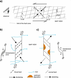
Figure 29 – Strike-slip tectonic regime faults. a) Strike-slip fault zone with a sense of left-hand movement, that is, from the observer’s position (eye to the left) the portion to the left of the eye moves toward viewer. The deformation is concentrated along the fault zone where strike-slip conjugate shear fractures develop. The conjugate fractures are also called Riedel shears R1 and R2. R1 represents the shear fractures that have the same sense of movement as the fault zone which is left-hand in this case. R2 are the shear fractures with the opposite sense of movement, i.e., right-hand. Bending or overlapping strike-slip faults may give rise to zones where b) shortening (transpression) and c) extension (transtension) are present across the domain at the same time as the directional displacements are occurring. Secondary thrust faults are restricted to the transpression zones b) while normal faults are restricted to the transtension zones c). Sediment deposition is likely to take place at the depressions that may form at transtension zones. The sense of the river flow indicates the position of highlands b) and lowlands c). These structures in the zones provide a connection between the otherwise separate faults. Moreover, depending on the stress magnitude, horizontal joints may be generated in the transpression zone while vertical joints may be generated in the transtension zone and they may favor groundwater flow (modified from Ramsay & Hubber, 1987).
The rock failure criteria, expressed by the Mohr-Coulomb and Griffith envelopes, imply that faults and joints are formed under different stress conditions and, therefore, cannot propagate at the same time. However, over time, if the orientation of the stresses is constant but their magnitudes change, the tectonic regimes can generate joints, when σ3 is tensile, and faults, when stresses are all compressive. Joints are perpendicular to σ3 and, therefore, in the extensional and strike-slip regimes they are vertical (Figure 30). In the compressive regime, horizontal joints can be formed when the fluid pressure causes the effective vertical stress to be tensile. Stress conditions similar to the ones in the compressive tectonic regime (a compressive horizontal stress and a vertical σ3 are thought to be associated with the generation of sheeting joints (Figure 26b,c), also called relief joints. These persistent and closely spaced joints are parallel to the topographic surface and found just below the ground surface down to depths of usually less than 100 m. These joints are observed, for example, in granites, gneisses and hard sandstones. The mechanisms for their generation are discussed in Section 3.6.
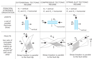
Figure 30 – Joint and fault dips formed in the three Andersonian tectonic regimes (extensional, compressive and strike-slip). The resulting deformations in the extensional and compressive regimes are horizontal stretching and shortening, respectively. In the strike-slip and extensional regimes, joints may be formed when σ3 is negative (tensile), and faults when σ3 is positive. The conditions required to form joints in the compressive regime are explained in the text. Although joints and faults can be formed in the same tectonic regime, they cannot be generated at the same time, as illustrated by the Mohr circle.
As the tectonic regime controls fracture orientations, it will also impose certain characteristics to the connected fracture network. This and other implications for groundwater flow, such as how depth influences the hydraulic conductivity of subhorizontal fractures and sheeting joints, are described in Section 3.2.