2.4 Stress Magnitude and Fracture Types
The magnitudes of the individual stress components control how the fractures initiate and propagate by shear or by opening modes. This relationship can be elegantly expressed by the Mohr circle that is illustrated in the Mohr diagram (Figure 14). Thorough descriptions of it can be found in textbooks on structural geology (Price & Cosgrove, 1990; Ramsay & Hubber, 1987; Fossen, 2016; and Davis et al., 2011, among others), and on rock mechanics (Jaeger & Cook, 1979; Goodman, 1989; Hudson & Harrison, 1997). In this book we use the convention that compressive stresses are positive and tensile stresses are negative.
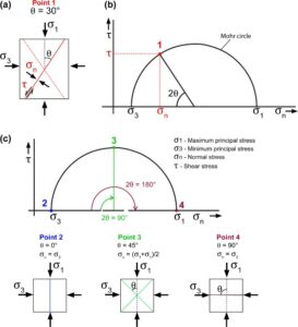
Figure 14 – Mohr circle and Mohr diagram showing how the magnitudes of the principal stresses, σ1 and σ3, are related to the shear and normal stresses that act on any plane at a given angle from σ1. a) Under certain values of compressive σ1 and σ3 stresses, a conjugate pair of shear fractures (stippled and continuous red lines) that undergo a critical state of shear (τ) and normal stress (σn) is formed. Each shear fracture makes an angle θ of approximately 30° with σ1. b) The Mohr circle diagram relates σ1 and σ3 with the normal stress (σn) and shear stress (τ) (x and y axes, respectively). At the stress state represented by Point 1, a pair of conjugate shear fractures is generated. These fractures make an angle of 30° with σ1, as shown in part a. c) Points 2, 3 and 4 represent stress states that do not generate fractures; they are just meant to show how planes with a specific θ angle with σ1 have specific locations (points) in the Mohr circle. Any state of stress, acting on any plane, with a specific angular relationship with σ1 and σ3, can be represented as a point in the Mohr circle; points 2, 3 and 4 are examples. Point 2 represents a plane perpendicular to σ3 (the normal stress, σn, is equal to σ3) and, consequently, parallel to σ1. Point 3 represents conjugate planes that make an angle of 45° with σ1. Therefore, as shown in the Mohr circle, 2θ is equal to 90°. Point 4 represents a plane that is perpendicular to σ1 (σn = σ1). This image is based on Cosgrove & Hudson (2016).
2.4.1 Shear Fracture
Planes perpendicular to the principal stresses have no shear stress. Planes that are not perpendicular to the principal stresses have normal stresses (σn) and shear stresses (τ) that are a function of the maximum and minimum principal stresses, σ1 and σ3. The values of σn and τ vary with the orientation of the plane, defined as an angle θ from the direction of σ1. Plotting σn versus τ delineates the Mohr circle in the Mohr diagram. Each point in the Mohr circle represents the state of stress in planes that have an angle θ with σ1 (Figure 15).
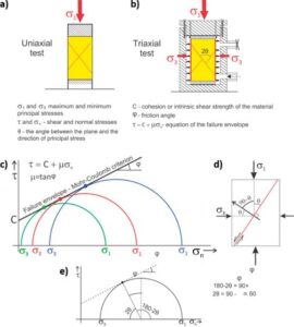
Figure 15 – Schematics of a) uniaxial (no lateral confinement) and b) triaxial (with lateral confinement) as based on Price & Cosgrove (1990) laboratory experiments, in which natural materials (soils and rocks) are subject to a specific amount of compression. Failure occurs at different combinations of specific values of σ1 and σ3 . c) Laboratory experiments demonstrate that the points on the Mohr circles that represent conditions at which failure (fracturing) occurs, are aligned along a straight line with a specific y-intercept C. d) The slope of the line (φ) usually varies from 25° to 40°, which implies that 2θ ranges from 65° to 50°. In a), b) and d) the red diagonal lines represent the shear fracture planes.
A shear fracture is formed when a state of critical stress, defined by the values of τ and σn, acts on a plane. Shear fractures, or faults, are mostly formed as conjugate pairs, and each shear fracture makes an angle θ of approximately 30° with σ1 = (Figure 15a).
Experimental analyses carried out through uniaxial and triaxial compression tests (Figure 15a,b) define the combinations of σ1 and σ3 values and the differential stresses (σ1 − σ3) necessary to promote the generation of a new fracture (failure). Figure 15c shows the Mohr-Coulomb failure envelope, which is defined by a line that is tangent to the Mohr circles. The tangent points (i.e., the points of the Mohr circle that touch the failure envelope) represent the stress states that lead to failure along specific planes. The slope of the linear failure envelope is the friction angle (φ).
The value of the shear stress at a zero normal stress (intersection of the y axis with the failure envelope) is called cohesion (C); this represents the material’s intrinsic shear strength, such as that produced by cementation in sedimentary rocks. Cohesion and friction angle are the two parameters that define the Mohr-Coulomb failure criterion. The friction angle (φ) has a very well-defined relationship with θ (Figure 15e). The angle 2θ shown in Figure 15e, and measured from the direction of σ3, is equal to 90 − φ. Assuming for example a typical value of φ = 30°, the acute angle between the two conjugate shear fractures formed under this condition would be equal to 60°. The angle θ, measured from σ3 in the Mohr circle, is also the angle between σ1 and the generated shear fracture (Figure 14). Structural geology books in general use this notation; however, in soil and rock mechanics textbooks, θ is defined as being the angle between σ1 and the normal to the fracture plane.
Figure 16 represents the conjugate faults (or shear fractures) that make an angle 2θ of approximately 60° with one another (Figure 16b) and 30° with σ1 (Figure 16c). The shear along the faults is noticeable by the offset of the two adjacent and parallel lines in Figure 16c. Conjugate faults are repeatedly associated in space, with important implications for the connection between fractures, as discussed in Section 2.6.
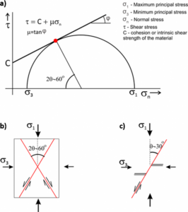
Figure 16 – Stress state associated with the formation of conjugate shear fractures. a) Mohr circle; the red point is represented in part b. b) The conjugate shear fractures make an angle 2θ of 60° with one another and 30° (θ) with σ1. c) The shear along the fractures is noticeable by the offset of the two close parallel lines (modified from Price & Cosgrove, 1990).
2.4.2 Extension Fracture
Extension fractures (joints) are perpendicular to the lowest principal stress σ3 and are formed when σ3 is tensile (negative) and equal to the tensile strength (T=”s19″ href=”#bookmark70″>) of the rock (Figure 17); this strength varies with lithology and is determined through laboratory experiments.
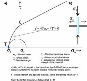
Figure 17 – Stress state associated with the formation of extension fractures (joints). a) The blue point represents the stress state at the formation of a joint; σ3 is negative and equal to the tensile strength of the rock. b) The joint is perpendicular to σ3 and parallel to σ1; the opening mode is represented by the separation of the two joint faces and no shear displacement takes place (modified from Price & Cosgrove, 1990).
The conditions of joint formation require a small differential stress, and σ1 may be positive, but of small magnitude, or even negative. Because joints are perpendicular to σ3, they consist of a set of parallel fractures, a distinguishing feature that allows them to be recognized in rock exposures.
The stress state needed for the formation of joints (σ3 is negative and equal to T) is expected to be more common in geological environments where the crust undergoes extension, such as regions where intraplate grabens are being formed, or at plate boundaries associated with rifting. However, joints can be abundant in several tectonic environments. The conditions for their formation can be met, for instance, by the presence of fluid overpressure, as discussed in Section 2.5.
2.4.3 Hybrid Fracture
Both hybrid and shear fractures form a pair of conjugate fractures. However, the angle between conjugate hybrid fractures is less than 45° and the propagation involves simultaneous shear and opening modes; the stress normal to the fracture (σn) is tensile (negative) as shown in Figure 18. The connection of the various points that represent the formation of hybrid fractures in the Mohr circle constitutes an envelope described by the Griffith criterion.
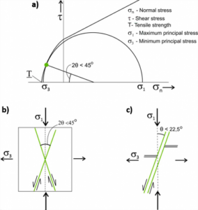
Figure 18 – Stress state associated with the formation of hybrid fractures. a) The green point on the Mohr circle represents the stress state at which the conjugate fractures (green lines) are formed. As these fractures undergo both shear and opening (with a σ3 that is negative and close to the tensile strength T of the material), they are classified as hybrid. b) The angle between the conjugate fractures is smaller than 45°. c) The opening mode is represented by the separation of the two fracture faces and shear displacement is represented by the offset of the two close and parallel lines (modified from Price & Cosgrove, 1990).
The combined Mohr-Coulomb and Griffith criteria yield the complete failure envelopes for a variety of materials (Figure 19). Rocks such as sandstone, marble and limestone have considerably smaller values of C and T, when compared to dolomite, diabase, and granite. Moreover, the inclination of the shear envelope (friction angle φ) also varies with rock type.
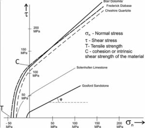
Figure 19 – Mohr-Coulomb and Griffith criteria failure envelopes for diverse materials. Rocks such as sandstone, marble and limestone have considerably smaller values of C and T when compared to dolomite, diabase, and granite. Moreover, the inclination of the shear envelope (φ) also varies with the rock (modified from Davis et al., 2011).