8.2 Exercises on the Interpretation of Fracture Data Collected in the Field and their Consequences for Groundwater Flow
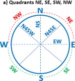
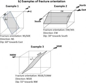
The following exercises (8 through 17) concern fracture formation (fracture types), tectonic regimes and orientation of the principal stresses that can be inferred from data, such as fracture orientation, collected by the authors during academic-related field work or informal excursions. The orientation (or attitude) of fractures displayed in photographs and sketches follows the quadrant notation because this is more readily understandable, even though books and articles generally use the dip-direction and right-hand-rule notations. Illustrations that explain the quadrant notation, along with three examples of fracture orientations, are shown in the images below. Part (a) of the image shows quadrants NE, NW, SW, and SE. Part (b) of the image provides examples of fracture orientation. Directions are expressed either as NS and EW or in terms of NW and NE quadrants. The dip direction is referred either to N, S, E and W or to one of the four quadrants. For instance, for an NS fracture, the dip is either to W or to E.