Exercise 2
Two different rock layers are represented in the block diagram below: dolomite (orange layer) and mudstone (green layer). Points D (dolomite) and M (mudstone) are both 3 km deep, and the average rock density above each one is the same. This rock mass is under lithostatic conditions, which means tectonic stresses are not present, i.e., the vertical and horizontal stresses are derived solely from the weight of the overlying rock column.
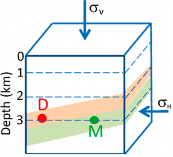
a) Calculate the vertical stress (σv) at points D and M in MegaPascals (MPa) using the following equation.
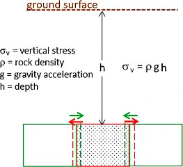
σv = ρ g h
where:
|
ρ |
= |
2,500 kg/m3 (average rock density) |
|
g |
= |
10 m/s2 (gravitational acceleration) |
|
h |
= |
3 km (depth) |
b) Calculate the horizontal stress (σh) in MegaPascals (MPa) which, under lithostatic conditions, is a fraction of σv and depends on the elastic properties1 of each rock as follows.
σh dol = σv/(mdol −1)
σh mud = σv/(mmud −1)
where:
|
σh dol |
= |
dolostone horizontal stress |
|
σh mud |
= |
mudstone horizontal stress |
|
mdol |
= |
5 (dolomite Poisson number) |
|
mmud |
= |
4 (mudstone Poisson number) |
c) Draw a Mohr diagram for each rock representing the stresses and the failure envelopes given the following equations
|
Failure envelope of the dolostone: τ = 75 MPa + 0.7 σn |
|
Failure envelope of the mudstone: τ = 15 MPa + 0.53 σn |
where:
|
MPa |
= |
Megapascal = 106 pascal |
|
MPa |
= |
1 N/m2 |
|
Pa |
= |
1 N/m2 |
|
N |
= |
1 (kg m)/s2 |
|
Pa = 1 [kg m/s2 ] = 1 Kg
|
||
d) Under this stress state, will the rocks undergo failure?
e) Which rock has the greater cohesion?
f) Which of the two rocks will fracture by shear mode under smaller differential stresses, that is, under milder tectonic conditions?
Supplemental information – Elastic Properties Explanation
The diagram below (based on Price & Cosgrove, 1990) depicts an elemental cube (stippled) in the Earth’s crust. The weight of rock column above the cube produces the vertical stress (σv) that causes an infinitesimal vertical compression (ev). If the cube were not confined laterally, as illustrated by the gray areas, the vertical stress would cause the cube to expand (red arrows) by a certain amount (represented by the red dashed lines). However, the rock beside the cube is also under the effect of the same vertical stress and tends to laterally expand by the same amount (green dashed lines), but in the opposite direction (green arrow). This situation prevents the expansion and simultaneously creates a horizontal stress that is a fraction of the vertical stress; the magnitude of this horizontal stress varies with the rock type. In the lithostatic condition, where all the stresses are derived from the rock column weight, the horizontal stress for stiffer rocks (when compared to softer rocks) is a smaller fraction of the vertical stress. This happens because the lateral expansion of stiffer rocks is smaller.
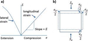
The elastic properties of the materials shown in the image below control horizontal stress in a lithostatic condition: a) the stress-strain relationship is linear; b) the elastic strains (ev, eh) are infinitesimal; and, Sz = vertical stress (Price & Cosgrove, 1990).
The simplifying premises of the elasticity theory are:
- The material is homogeneous.
- The material is isotropic (its properties do not vary with the direction).
- The elastic strains (deformations) are infinitesimal (limit ~3 percent).
- The stress–strain relationship is linear and expressed by the ratio S/e = E, where:
|
E. |
= |
Young’s modulus (material constant) |
|
eh/ev |
= |
ν, Poisson’s ratio |
|
1/ν |
= |
m, Poisson’s number |
and Sz is vertical stress (based on Price & Cosgrove, 1990, pages 18-20).
Supplemental information – Stress State Explanation
The following Mohr diagrams (Fossen, 2016) represent a) stable and b) unstable conditions.
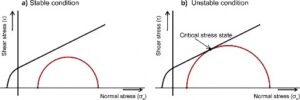
In diagram a, the Mohr circle does not intersect the failure envelope because the principal stresses are not large enough. This is a stable situation in which no fractures are formed. In diagram b, the principal stresses are such that the Mohr circle intercepts the failure envelope at one point (critical stress state) at which shear conjugate fractures are generated. Because fractures are formed, this is called “unstable condition.”