Exercise 7
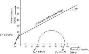
A mudstone at 3,000 m depth is under a stress state represented by the Mohr circle shown below, in which the vertical (σv°) and horizontal (σh°) stresses correspond to σ1 and σ3, respectively. At this stress state no faults are formed because the circle does not intersect the failure envelope of the mudstone. Given the state of stress at the depth of 3,000 m in the mudstone, where σv = 75 MPa, σh = 30 MPa, C = 15 MPa and φ = 28o, develop the following:
a) Represent the Mohr circles that correspond to the formation of normal and thrust faults in the mudstone at the given depth.
b) Determine the dip of each type of fault.
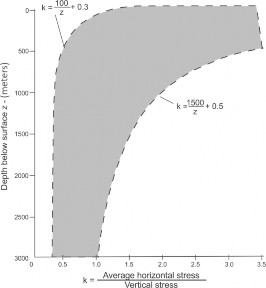
c) The graph below (modified from Hoek & Brown, 1980) shows in-situ stress from several regions throughout the globe. Close to the surface (above 500 m in depth), the average horizontal stress can be on the order of three times larger than the vertical stress. Analyze the graph and explain at what depths the thrust faults tend to be formed and what consequences this may have for the flow. Information required to complete (a) and (b) of the exercise is given below (Supplemental Information).
Supplemental information – Determination of Stress State Acting on a Plane
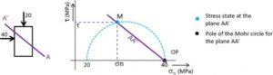
On the left side of the image below, line AA’ represents a plane that makes an angle with the main stresses (20 and 40 MPa). The stress state acting on this plane is determined by drawing a line on the Mohr diagram with the same slope and passing through its pole (OP); the stress state on the plane AA’ is given by point M. The determination of a plane pole is explained below.
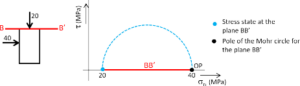
Supplemental information – Determination of the Pole of a Plane
Start with a plane having a known stress state, e.g., a horizontal plane as shown by the red line in the image below, for which the values of σ1 (40 MPa) and σ3 (20 MPa) are known. Next draw the Mohr circle in the Mohr diagram. Draw a horizontal line (BB’) on the Mohr diagram that starts at its state of stress (20,0; blue point) and continues until it intersects the Mohr circle again; this second point of intersection is the pole (OP).