Solution Exercise 16
All the necessary information to answer the questions of this exercise can be found in Figure 10 , Figure 21 and Figure 30 of this book. The image below illustrates all three fracture sets in one block diagram with respect to their orientation and the stresses at the time of their generation.
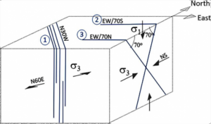
a) The parallelism of the fractures of set 1 (average orientation = N30–35W/ 85NE) and the associated dikes indicate an opening propagation mode. The dikes were emplaced because of the space created by the opening mode.
b) Joints are perpendicular to σ3, so this stress at the time the NW joints were formed must have been horizontal. This is consistent with both extensional and strike-slip regimes.
c) The minimum principal stress σ3 is horizontal and, because it has to be perpendicular to set 1, it must strike N60E on average. The available information is not enough to know whether the maximum principal stress, σ1, was either horizontal (strike-slip regime) or vertical (extensional regime).
d) Sets 2 and 3 form a typical conjugate pattern of the extensional regime because they have the same direction (EW) and dip around 60–70° in opposite senses (set 2 dips toward south and set 3 toward north). So, sets 2 and 3 are faults that have propagated through shear.
e) In the extensional regime, σ3 is horizontal and perpendicular to the strike of the faults, which means that σ3 strikes NS. In addition, σ1 is vertical and σ2 is horizontal and parallel to the strike of the faults.
f) Fracture set 1 was formed by the opening mode. However, this alone cannot be taken as an indication of a larger present-day aperture. On the other hand, the weathering of the dikes that infill the fractures of set 1 is an indication that flow along those fractures is currently taking place. Thus, K of set 1 is likely larger than the K of sets 2 and 3 because the surfaces of the latter are fresh and do not show any other evidence of flow. This means that greater K can be expected along the direction N30W. As the fracture zones of set 1 are vertically persistent (>80 m), the groundwater flow system may be well connected. The orientation and persistence of the three fracture sets favor connectivity. However, the spacing of set 1 fracture zones can be as large as tens of meters. The prediction of where these zones are and how they control preferential flow paths is a challenging task.