Box 1 Simulating Lake Conceptual Models, Winter’s Models
The early work of Winter in the 1970’s made an important contribution to conceptualizing lakes in the larger groundwater system. Winter (1976) simulated conceptual models of lakes and groundwater exchange using two-dimensional cross sections orientated parallel to groundwater flow and also in three dimensional models (Winter, 1976; Winter, 1978). This work explored how theoretical groundwater flow and exchange would occur using cross sections constrained by vertical side hydraulic divides and a no-flow boundary at the base. The simulated sections could represent anisotropic sediments, be assigned various hydraulic conductivities, and allow for variation in the position of the water table (Figure Box 1-1). Models were simulated under steady-state conditions.
Figure Box 1-1 – Numerical two-dimensional model boundary conditions and parameters used by Winter (1976) to simulate lake exchange and groundwater flow. Both a single-lake and a three-lake model was developed. Hydraulic conductivity values were assigned as Kx and Kz resulting in anisotropic conditions. The water table was assigned as fixed head values, and left, right and bottom boundaries were assigned as zero flux, no-flow. In some models, a rectangle of sediment with differing hydrogeologic properties was included in the simulation, labeled Aquifer in the image (Winter, 1976).
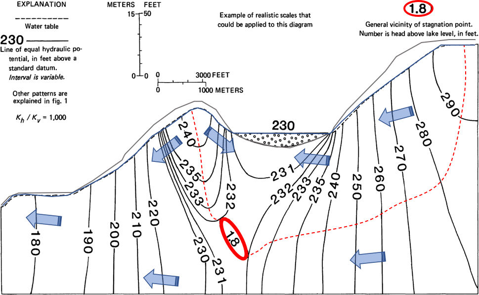
This exercise provided insight into how groundwater and lakes may interact. For example, in the setting shown in Figure Box 1-2, the lake is influenced by the adjacent local flow systems and the regional groundwater flow continues below the lake as hydraulic divides and stagnation points are formed. Winter (1976) describes a stagnation point as “a point on the divide (between flow systems) at which the head is a minimum compared to every other point along the divide”. … “It is a point in the flow field at which vectors of flow are equal in opposite directions and therefore cancel … The stagnation point is a point of diversion of ground-water-flow paths.” In Figure Box 1-2, the minimum head along the local groundwater divide is 1.8 ft (0.5 m) higher than the lake elevation. When groundwater and lakes are not separated by a hydraulic divide and stagnation point, flow to and leakage from a lake may occur, i.e., mixed exchange (Figure Box 1-3).
Figure Box 1-2 – Cross section of groundwater flow in a topography with hills (brown line represents land surface/lake bottom; blue line is the water table) and a lake. The lake is effluent or gaining as groundwater locally flows into the lake. Groundwater flow lines are not represented as the system is anisotropic and vertically exaggerated by 80%. Large blue arrows show general groundwater flow. The red dashed line is an approximate representation of the hydraulic divide separating the local and larger more regional groundwater flow system. The heavy red line surrounds an area in which a stagnation point separates local and regional groundwater flow. The head at the stagnation zone is the lowest head on the hydraulic divide but still higher than the lake stage, here 1.8 ft higher (modified from Winter, 1976).Figure Box 1-3 – Cross section of groundwater flow in a topography with hills (brown line represents land surface/lake bottom; blue line the water table) and a lake. The lake is receiving local groundwater and would be generally considered an effluent or gaining lake. However, the presence of a high hydraulic conductivity horizontal aquifer (stippled horizontal rectangle, Kaq) creates a flow system with no stagnation points. This set of conditions results in water being lost from the lake through the bottom of the lake (mixed lake setting). Flow lines are not represented as the system is anisotropic and vertically exaggerated by 80%. Blue arrows illustrate the general groundwater flow direction (modified from Winter, 1976).
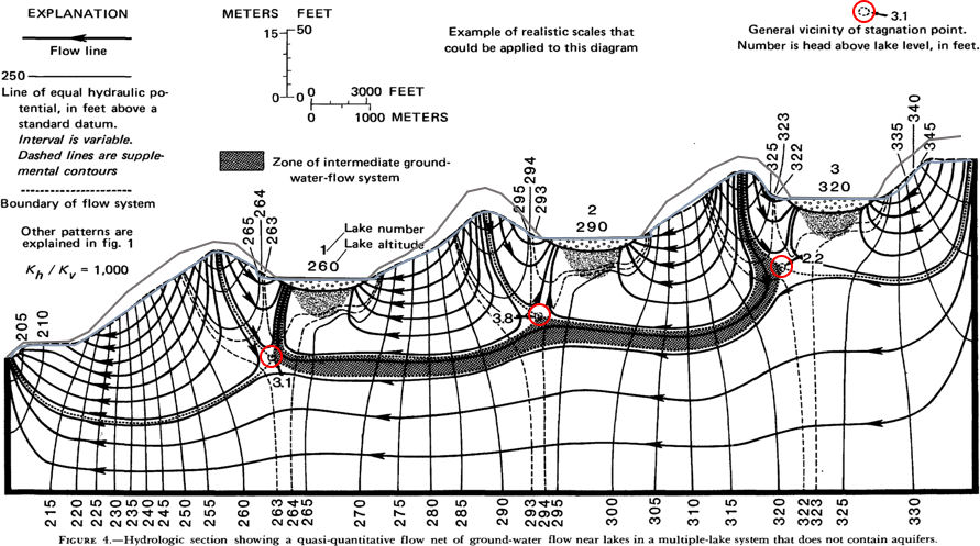
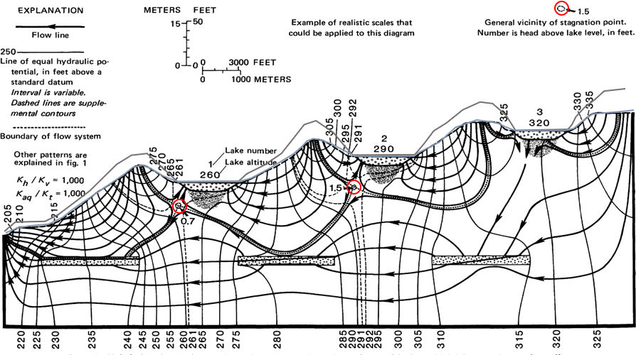
Winter (1976) also examined a landscape cross section with three lakes and presented conceptual models showing how these lakes interface with the groundwater flow system (Figures Box 1-4 and 1-5). Note, when multiple flow systems are present, lakes can receive flows from local and intermediate flow systems. A lake located at the regional discharge point on the left side of the land scape (Figure Box 1-4) would receive recharge from local and intermediate flow systems as well as the regional flow system. Further review of this early work and Winter (1978) will provide the reader with insight into the complexity of lake-groundwater exchange.
Figure Box 1-4 – Cross section of groundwater flow in a topography with hills (brown line represents land surface; blue line the water table) and lakes. Lakes 1, 2 and 3 are all effluent or gaining lakes. Lakes 2 and 3 are exchanging groundwater with local flow systems and lake 1 receives water from both local and intermediate flow systems. Black flow lines are schematic showing general directions of flow as the system is anisotropic and vertically exaggerated by 80% (modified from Winter, 1976).Figure Box 1-5 – Cross section of groundwater flow in a topography with hills (brown line represents land surface; blue line the water table) and lakes. Lakes 1 and 2 are illustrated as effluent or gaining lakes fed by local groundwater flow. Lake 3 receives local discharge and it is also losing water to the regional flow system (mixed system). Flow lines are schematic showing the general direction of flow as the system is anisotropic and vertically exaggerated by 80% (modified from Winter, 1976).