5 Geomechanical Processes Related to Anthropogenic Land Subsidence
Apart from compaction or expansion, pore pressure change in the pumped or injected formation may induce other geomechanical processes, for example, the generation of local fractures that may extend to the ground surface, reactivation of preexisting faults, with a sharp increase in hydraulic conductivity, and reduction in strength. The consequences may greatly affect surface structures and infrastructures and expose aquifers to the risk of contamination.
The description of these mechanisms can be done with the aid of the Mohr‑Coulomb representation of the effective stress state in the (σ,τ)‑plane as shown in Figure 29, where compressive stresses are marked as positive. When water is removed, the pore pressure p decreases with respect to the original value (p < p0) and the effective stress σ increases in accordance with Terzaghi’s principle. Hence, Mohr‑Coulombs circle moves right‑ward, that is, farther from the shear‑τ‑axis and generally, from the failure line bounding the envelope of the allowable stress states. In contrast, when fluid is injected p rises and may exceed p0. In this case, the effective stress falls below the original in situ value, with Mohr‑Coulombs circle moving left‑ward, that is, toward the τ‑axis and generally, the failure line. It is worth pointing out that during both pumping and injection, the maximum (σ1) and minimum (σ3) effective stresses may follow different paths, possibly creating an increase in the diameter of Mohr‑Coulombs circle that approaches the failure line as shown in Figure 29 (Teufel et al., 1991; Segall and Fitzgerald, 1996). Notice that external stresses, that is, tectonic stresses, are assumed to be constant over the time period of an aquifer or reservoir production life (a few decades as a maximum). By distinction, the principal stress orientation and the ratio σ1/σ3 change significantly with depth (Zoback, 2007).
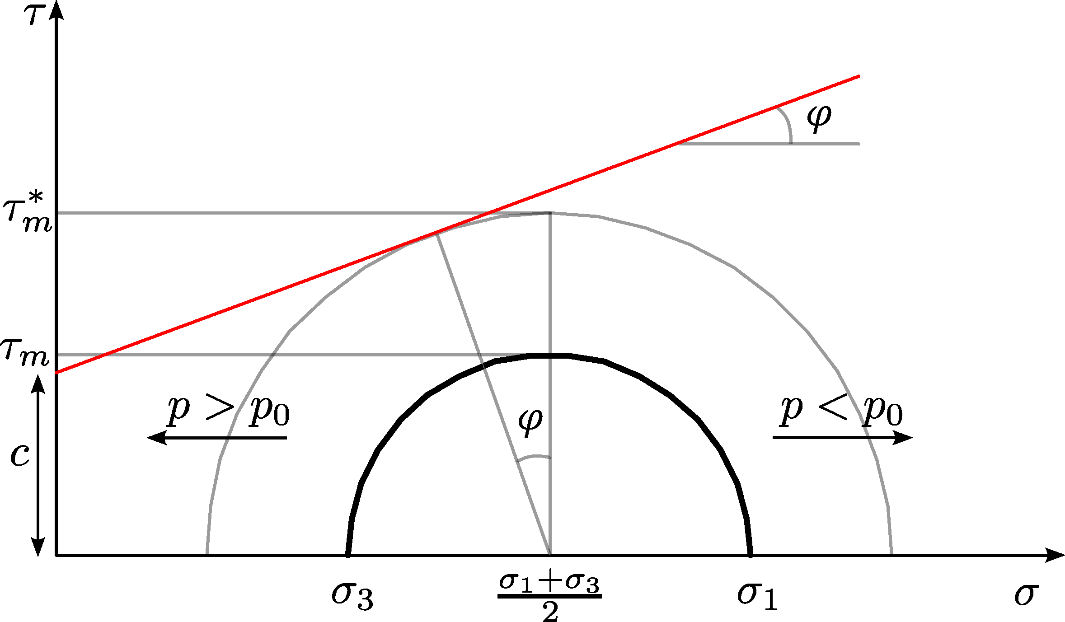
Figure 29 ‑ Mohr‑Coulomb’s circles. When the pore pressure p increases because of fluid injection, the circles move left‑ward and may achieve the limiting yield surface or friction line τ = c + σtanφ where σ and τ are the normal and shear stress, respectively, c is the cohesion and φ is the friction angle. τm and τm* are the current largest and maximum allowable shear stress, respectively, σ1 and σ3 are the maximum and minimum principal stress, respectively.
Two failure mechanisms may occur: a) if Mohr‑Coulombs circle touches the envelope line a shear failure may ensue or a preexisting fault/thrust may be activated, and b) if Mohr‑Coulombs circle crosses the τ‑axis a tensile failure takes place. Moreover, a dilation (or dilatancy) phenomenon may be induced, that is, an increase in volumetric strain due to shear, increasing the magnitude of the injected formation’s expansion. Shear dilation accompanies yield and strain weakening with permanent alteration in the fabric of the fluid‑bearing stratum through irreversible deformation, grain rearrangement, permeability change and porosity increase, potentially contributing to a measurable rebound of the land surface (Zoback, 2007).