3.5 Fiber Optics
Following the development and large use for monitoring civil infrastructures, distributed fiber optic sensors (FOS) have become even more popular in the recent years to perform real‑time observations and provide early warning of natural and anthropogenic geo‑hazards, such as landslides (Schenato et al., 2017), debris flows, land subsidence (Wu et al., 2015), and earth fissures (Liu et al., 2017). The common assumption that enables the sensing feature in optical fibers is that the surrounding environment affects the local properties of the fiber itself: the back‑propagating light generated when an optical signal is fed into the fiber is used to investigate the local properties of the fiber, and therefore to figure out the changes in the surrounding environment. Very simply, local temperature and strain intrinsically influence frequency and intensity of the scattered signal and therefore variations of temperatures, displacements, loads, earth pressures, pore water pressures and soil moistures can be captured with high accuracy. Schenato (2017) and Zhu et al. (2017) provide accurate reviews of the state‑of‑the‑art.
In Japan, a FOS system has been introduced in boreholes to monitor formation compaction accompanying the exploitation of natural gases (Ikeda et al., 2015). Wu et al. (2015) initiated a study on applying FOS to land subsidence monitoring in Suzhou, China, where a complex multi‑aquifer system has been over‑drafted during recent decades. The fully distributed strain sensing cables were vertically installed in boreholes for displacement monitoring. The borehole was filled with a fine sand‑gravel‑bentonite mixture after the cables were installed, and no strategies for temperature compensation were adopted. The displacements were calculated based on the axial strain measurements of the cables.
Liu et al. (2017) investigated the feasibility of using fixed‑point distributed optical fiber sensor in earth fissure monitoring. To improve the fiber strength, the structure of the cable was made of three layers from the core to the outer coating materials: the bare‑optical fiber, a polyurethane coating, and a spiral‑shaped metal sheath. Five‑centimeter‑long sections of cable were further encased into an aluminum alloy tube and placed in a heat‑shrinkable tube (10 cm‑long) at regular distances. These raised portions of cable were used to anchor the cable to the ground with nails. The distance between anchors was fixed to 2 m after careful consideration, and the cable was pre‑stressed during installation. Additional strain‑free cables were measured for temperature compensation. The sensor system was successfully used in an earth fissure site in Wuxi, China, where two main ground fissures (with a maximum strain value of 360 με, that is, 36010‑6) were detected and measured (Figure 26).
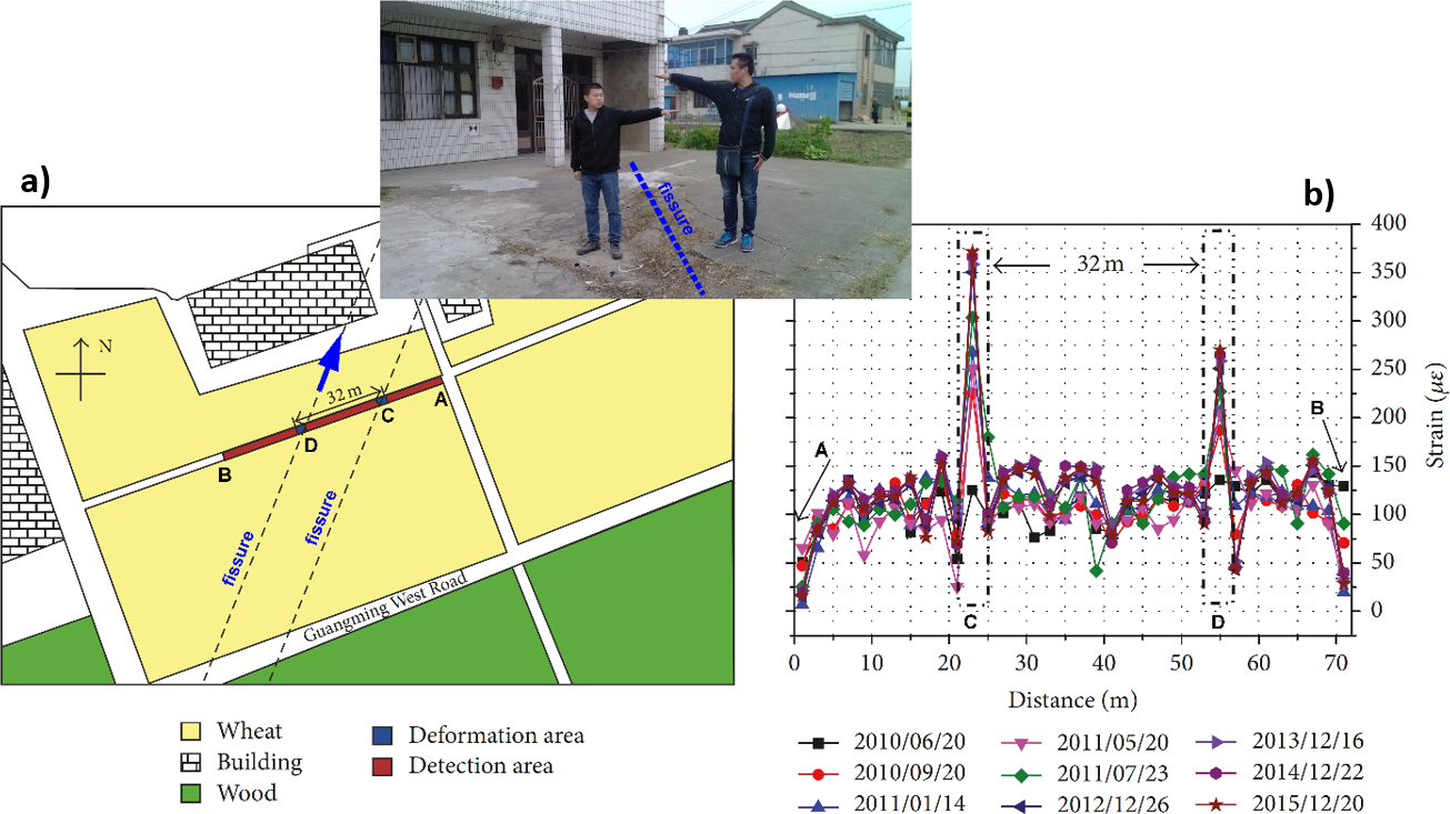
Figure 26 ‑ a) Map with the trace of the earth fissures in Wuxi, China, and the location of the FOS monitoring equipment. The blue arrow represents the orientation of the photo shown in the inset. b) Strain distribution along the cable: the two peaks correspond with the main ground fissures (modified after Liu et al., 2017).