2.1 Darcy’s Law
In 1856, Henry Darcy published results of sand column experiments he performed to better understand principles of water flow through filter beds, which were used in the design of water supply systems in Dijon, France (Darcy, 1856). As a result of the experiment, Darcy discovered a mathematical relationship relating flow to hydraulic gradient. This mathematical relationship is now referred to as Darcy’s law; it is the fundamental equation describing the flow of fluid through porous media, including groundwater. He discovered that the water flow rate through a sand packed column was a linear function of the hydraulic head loss across the filter bed and not just the difference in water pressure. Besides its relevance to groundwater hydrology, Darcy’s law forms the quantitative basis of many science and engineering disciplines including soil science, civil engineering, petroleum engineering, and chemical engineering. Darcy’s law is fundamental to understanding and predicting the behavior of groundwater flow and is the basis for interpreting measurements such as water levels in wells.
Consider the experimental apparatus shown in Figure 1. Although the experimental design is not the same as Darcy’s, the apparatus is analogous in that the hydraulics and mathematical relationships born by Darcy’s experiment are the same.
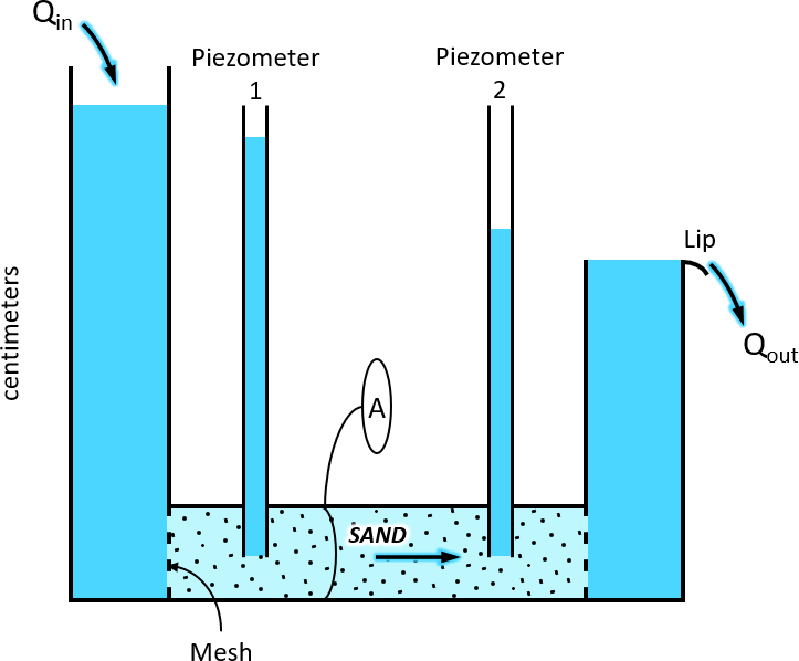
Figure 1 – Experimental apparatus for the illustration of Darcy’s law. A is the cross-sectional area of the sand-filled cylinder, Qin is the flow into the apparatus, and Qout is flow out of the apparatus (Cohen and Cherry, 2020).
The apparatus consists of a cylinder of cross-sectional area, A, that is filled with a porous medium such as sand. Water is introduced slowly into the left vessel and gradually flows through the sand-filled cylinder until the pore spaces in the sand are fully saturated. The water levels in each vessel continue to rise until the water level in the right vessel reaches the top and begins to flow over the lip. In this way, although water continues to be introduced into the left vessel, the elevation of the water column on the right side remains fixed. The water level in the left vessel continues to rise until the inflow rate, Qin, is equal to the outflow rate, Qout, at which time the elevation in both vessels stabilize. That is, steady–state flow conditions are established, and Q is the volumetric flow rate of water through the cylinder (i.e., volume per unit time, such as cubic meters per second, gallons per minute, liters per second).
Piezometers (in this case, small-diameter open tubes) are inserted into the cylinder. The upper end of each piezometer is open to the atmosphere, and the lower end is screened such that water can enter, but sand grains cannot. Upon insertion, the water level in each piezometer rises to a stable elevation. The elevation of the water measured in each piezometer represents the hydraulic head at the point of measurement, which in this case is the open end of the piezometer in the sand. Later, we will explore the various components of hydraulic head in porous media, which consists of the pressure at the point of measurement due to the water column above it, and the elevation of the point of measurement. As we will discuss further, pressure measurements alone are not sufficient to evaluate groundwater conditions.
Figure 2 is an abbreviated representation of the experimental setup that provides a framework to describe Darcy’s law. If we set an arbitrary datum at elevation z = 0 (for example, mean sea level), the water elevations in the piezometers are h1 and h2. The distance between the piezometers is ΔL.

Figure 2 – Illustration of hydraulic gradient based on two measurement points. Hydraulic gradient is defined by the distance between the piezometers and the difference in hydraulic head (Cohen and Cherry, 2020).
Darcy’s law (Equation 1) states that the volumetric flow rate, Q, is proportional to: (1) the difference in hydraulic head along a length interval, ΔL; (2) a coefficient K (hydraulic conductivity), which accounts for restriction to flow imposed by the solid medium and for the density and viscosity of the fluid flowing through the porous medium (in this case, water through sand); and (3) the cross-sectional area perpendicular to the flow direction:
 |
(1) |
The negative sign accounts for the fact that we define flow as positive in the direction of decreasing head (water flows from higher elevations to lower elevations). For example, in Figure 2, the term h2-h1 is negative, so introducing the negative sign results in a positive value for Q.
The nature and properties of hydraulic conductivity are described in more detail in the Groundwater Project book by Woessner and Poeter (2020). The term (h2-h1)/ ΔL can be expressed more generally as the hydraulic gradient as shown in Equation 2.
 |
(2) |
Hydraulic gradient is often denoted with an i, which is represented by the slope of the dashed line in Figure 2. Darcy’s law can therefore be expressed as Equation 3.
 |
(3) |
Darcy’s law applies to laminar (non-turbulent) flow conditions, meaning that the rate of water flow is slow enough that the trajectories of water particles do not crisscross as they migrate through the interconnected voids of the porous media. By “water particle”, we mean an aggregate of water molecules occupying a sufficiently small volume such that it can migrate through the interconnected network of pore spaces without separation. This volume may be on the order of cubic micrometers or less. Darcy’s law is discussed in depth by Woessner and Poeter (2020).
Having established the basic relationship described as Darcy’s law (Equation 3), note that the hydraulic gradient is independent of the absolute elevation of the water level. As shown in Figure 3, the gradient is based only on the relative difference in head and not on the magnitude of each head value.
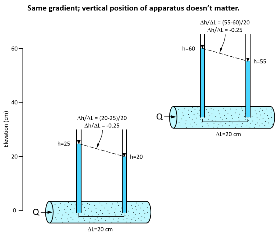
Figure 3 – Illustration showing that the hydraulic gradient (Δh/ΔL) does not depend on the absolute elevation; it only depends on the relative head difference (Cohen and Cherry, 2020).
In addition, Darcy’s law is independent of the orientation of the apparatus, because flow occurs in the direction of the hydraulic gradient. For example, as shown in Figure 4, the magnitude of the hydraulic gradient is the same in each case and the flow direction is always parallel to the apparatus.

Figure 4 – Different apparatus orientations with the same hydraulic gradient: the gradient magnitude (Δh/ΔL) is the same in each case and the gradient direction is parallel to the tube in each case. Darcy’s law is independent of the apparatus orientation, so the flow rate, Q, is the same in each case, and the flow direction is the same, in this case, parallel to the apparatus (Cohen and Cherry, 2020).
Figure 4 also illustrates an important aspect regarding how we interpret hydraulic gradient measurements, and it is worth noting early on. In the cases shown above, the gradient is defined with reference to ΔL, which is the distance between the measurements along the flow path. However, in practice, when we measure water levels in existing wells or install new wells to measure hydraulic gradient, we may not know the flow direction (in fact, flow direction is one of the most fundamental characteristics of groundwater we are trying to ascertain). Consider the various cases shown in Figure 4; if we were unable to observe the orientation of the cylinder, all we could deduce from the head measurements is that there is some component of flow in the horizontal direction (towards the right), and it is clearly possible that the flow could also have an upward or downward component. In fact, we can imagine the case where the inclination of the cylinder is even steeper than the cases shown, such that flow could be nearly vertical. This mental exercise points out a critical consideration needed to interpret hydraulic head data to infer flow direction. That is, we need to have some knowledge or assumptions regarding other factors that affect flow. In this case, it is the orientation of the confining boundaries (i.e., the sides of the cylinder); such knowledge provides a framework upon which we can interpret the head data. Later in this book, we discuss other factors regarding interpretation of water level elevations in wells, such as spatial variation of hydraulic conductivity and the location and type of recharge and discharge zones, because these must be considered in order to properly interpret hydraulic head data.