
Exercise 16
The image shown here is a map of the locations of several wells. The number next to each well is a measured hydraulic head in that well (in m ASL). Wells PW‑2 and PW‑5 are pumping wells. As shown on the map, observation well OW‑2 is 150 meters from pumping well PW-5 and 260 meters from PW-2.
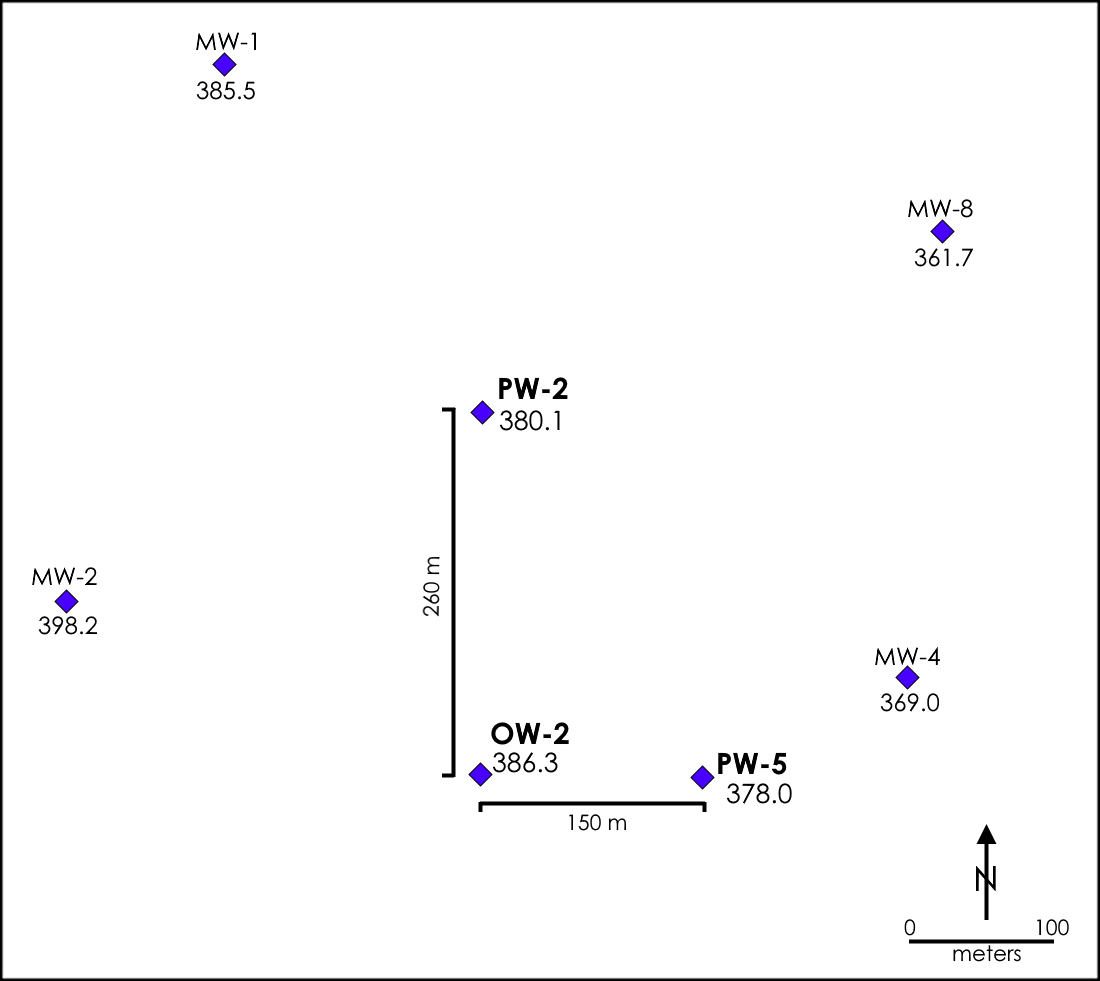
Assume the following:
- All wells are completed into the same confined aquifer.
- The elevation of the top of the aquifer is 55 m ASL.
- The elevation of the base of the aquifer is 25 m ASL.
- [latex]K =[/latex] 7.6 x 10⁻⁶ m/s
- [latex]S_{s} = [/latex] 0.000001/m
Using the information provided:
- Calculate the drawdown and hydraulic head in OW‑2 assuming that PW‑2 is pumped at a constant rate of 500 m3/d for 20 years.
- During the final 10 years of the pumping period for PW‑2, well PW‑5 is also pumped at a constant rate of 200 m3/d. Calculate the drawdown in OW‑2 associated with pumping PW‑5 for 10 years, then determine the final hydraulic head in OW‑2 assuming 20 years of pumping at 500 m3/d in PW‑2 and 10 years at 200 m3/d in PW‑5.