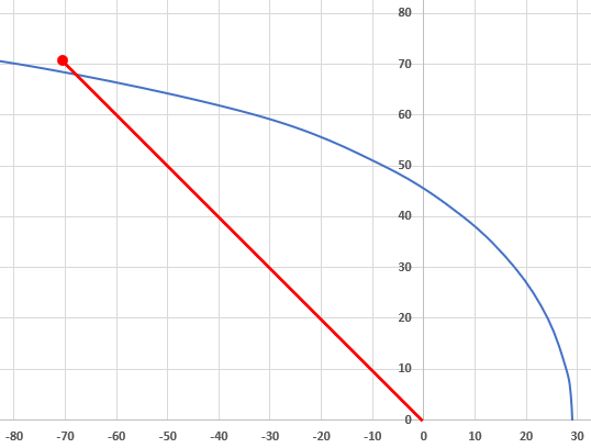
Solution Exercise 26
- The capture zone reaches a maximum width at which the regional flow is equal to the discharge of the well. The maximum width can be calculated using Equation (101).
[latex]B = 2y_{max =}\frac{Q}{Kib} = \frac{0.005\ \frac{m^{3}}{s}}{{5.5x10}^{- 3}\ \frac{m}{s}\ {2.5x10}^{- 4}\ \frac{m}{m}20\ m} = \mathbf{182\ m}[/latex]
So, the maximum half width of the capture zone is 91 m.
- The stagnation point location is given by Equation (100).
[latex]x_{o} = \frac{Q}{2\pi Kib} = \frac{0.005\ \frac{m^{3}}{s}}{2\ \pi\ {5.5x10}^{- 3}\ \frac{m}{s}\ {2.5x10}^{- 4}\ \frac{m}{m}20\ m} = \mathbf{28.9\ m}[/latex]
downgradient of the well.
- If the spill is 100 meters to the northwest of the well then it is at a location that is, by Pythagorean’s theorem at coordinates (-70.7 m, 70.7 m) relative to the well. That is, x = square root of half the hypotenuse squared. Or the square root ((100 m) (100 m) /2) = 70.7 m.
The relationship between the position x relative to the well and the half width, y, of the plume is given by Equation (102).
[latex]x = \frac{- y}{\tan\left( \frac{2\pi Kiby}{Q} \right)}[/latex]
The x location where the plume is 70 m wide is
[latex]x = \frac{- 70.7\ m}{\tan\left( \frac{2\ \pi\ {5.5x10}^{- 3}\ \frac{m}{s}\ {2.5x10}^{- 4}\ \frac{m}{m}20\ m\ 70.7\ m}{0.005\ \frac{m^{3}}{s}} \right)} = - 84.3\ m[/latex]
Consequently, the current capture zone does not lie beneath the spill so no adjustment of the pumping rate is needed, however given that it is so close to the capture zone, pumping might be slightly reduced to provide a factor pf safety. A sketch of the capture zone with a 100-meter line extending to the northwest showing the pint of the spill is shown here.