
3.2 The Cone of Depression Under Steady‑State Conditions
If as a well is pumped and drawdown ceases (i.e., the heads within the cone of depression are not changing with time) the system has reached a steady‑state condition. At steady state the constant flow of water from the well originates from a recharge source that is intercepted by the cone of depression.
Steady‑state conditions most commonly occur in confined groundwater systems when leakage from aquitards and aquifers that overlie or underlie the confined system, or from a boundary—such as a transmissive fault or lake in direct communication with the aquifer—provides water to the aquifer being pumped (Figure 7). Water levels stop declining (Figure 8) when the leakage rate (water entering the pumping unit) becomes equal to the pumping rate (Figure 9). In an unconfined system, steady‑state conditions occur when an adjacent recharge source equals the discharge rate at the well (Figure 9). As the water levels defining the cone of depression are not changing with time, none of the discharge water originates from the release of stored water within the aquifer being pumped. Instead, it is derived from external sources.
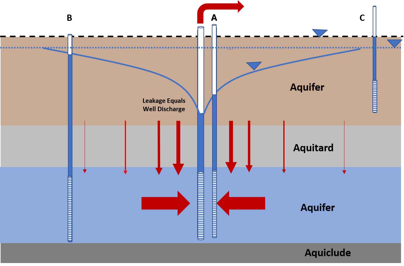
Figure 7 – Steady‑state conditions for a well pumping in a confined aquifer (blue). The dashed blue line is the corrected static water level for the confined aquifer and the dashed black line is the corrected static water level for the overlying aquifer. The overlying confining bed (aquitard) is sufficiently permeable such that as the cone of depression forms in the confined aquifer, vertical gradients between the overlying aquifer/aquitard and the pumped aquifer allow leakage to the pumped aquifer (vertical red arrows). In this example, leakage rates equal the pumping rate, drawdown in the aquifer being pumped has ceased, and the cone of depression is no longer expanding. Schematic drawdown curves for the pumping well and observation wells A and B are shown in Figure 8.
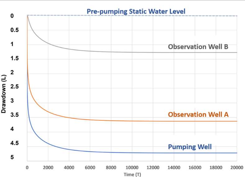
Figure 8 – Schematic of the occurrence of steady‑state conditions during pumping of a confined aquifer that over time captures a recharge source that equals the well discharge. Drawdown in the pumped well and observation wells ceases, that is the water levels stabilize. Well, locations are shown in Figure 7. Drawdown has dimensions of length (e.g., units of m, ft) and time may be in units of seconds, minutes, hours, or days depending on the length of the test and properties of the system tested.
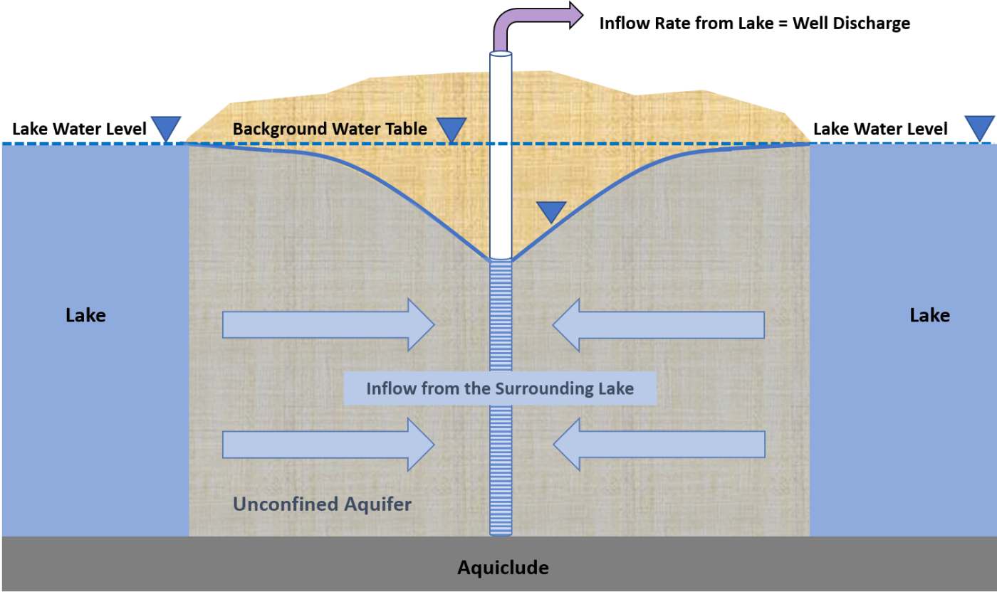
Figure 9 – Illustration of steady‑state conditions in an unconfined groundwater system where pumping occurs at the center of a circular island surrounded by a lake. Inflow from the lake equals the pumping well discharge rate. As a result, drawdown stops, no water is released from storage, and all water comes from the lake.