
4.4 Pumping Test Components and Design
In preparation for conducting the pumping test, the desired pumping rate and test length, the type and capacity of the pump used to stress the groundwater system, and the power supply should be identified.
Selecting the Pumping Rate
Planning the target discharge rate for the test is partly dependent on the thickness, extent, and hydraulic properties of the hydrogeologic unit being pumped, the hydraulic constraints of the pump selected, and the anticipated duration of the test. The target pumping rate is usually based on either the target well yield (in the case of a water supply well), the capacity of the pump or preliminary calculations of the estimated maximum drawdown in the pumping well (for example, pumping at 2,000 L/minute will likely draw the pumping well‑water level down 30 m over 6 hours of pumping). The likely amount of drawdown for a prescribed test period can be estimated using reported field values of transmissivity (T) and storativity (S) for units of similar lithology and thickness, or at other locations where the water‑bearing unit was tested. These data are substituted into analytical or numerical models to compute drawdowns for selected yields and a user specified test duration.
Another approach is to conduct one or more short pumping tests or step‑drawdown tests prior to conducting the main test. When little is known about how the formation will respond to pumping, these tests may be performed to observe drawdown versus time at different pumping rates. Step‑drawdown testing is discussed in Section 12.4. In brief, it involves pumping the well at a few different rates for a short period of time and monitoring the water levels for a short period of time. For example, sequentially pumping the well at 500 L/min, 2000 L/min, and 5,000 L/minute with each step lasting 30 to 60 minutes. Based on the step‑drawdown test results, an optimum pumping rate for a long‑term pumping test can be estimated as described in Section 12. When nearby observation wells are also monitored, water‑level trends near the end of the test in the pumping well and at observation wells can be extrapolated to estimate drawdown values at the end of the planned test. A second approach to estimating drawdown at the end of the planned test is to apply analytical tools to compute aquifer property values and then calculate the response of the hydrogeologic unit to the planned pumping rate.
Selecting the Duration of the Pumping Test
The length of a pumping test (which will also be the length of time for monitoring recovery after pumping stops) is dependent on the stated purpose. Principally, tests are conducted to determine the hydraulic properties of the tested water bearing unit, T and S. Other tests may be designed to determine if steady‑state conditions will occur (e.g., Kruseman & de Ritter, 2000) or if distant boundaries exist that will affect long‑term well performance and the magnitude of drawdowns.
Drawdown should be measured after the pumping has stopped (time‑recovery data) until water levels have recovered to within 90 percent of the corrected static water level at the beginning of the test. This typically occurs over the same length of time that pumping occurred (total test time for a 2‑hour pumping test would be about four hours). Longer tests are usually required to account for aquitard leakage and the delayed water‑level response commonly seen in unconfined systems. USEPA guidelines recommend pumping tests should last at least 24 hours with water level recovery data collected in the following 24‑hour period, resulting in a 48‑hour test period (Osborne, 1993).
It may be desirable to examine if pumping will result in water‑level changes reaching steady‑state conditions. Such pumping tests may require days to weeks to complete. Kruseman and de Ritter (2000) caution that inexperienced hydrogeologists may interpret that steady‑state conditions have occurred when the drawdown rates become small yet the cone of depression is still expanding. A true steady‑state condition is not realized until a recharge boundary or confining bed leakage equals the pumping rate. In unconfined systems delayed yield causes water levels to appear to stabilize, however, this is a temporary condition that can last minutes, hours, or days. Otherwise, the cone of depression keeps expanding, though slowly. It is recommended that pumping tests of unconfined aquifers should last up to three days in an attempt to avoid misinterpreting drawdown responses (Kruseman & de Ritter, 2000). Often regulatory requirements related to identifying the response of the groundwater to the pumping of a production well are conducted for a period of 72 hours (with a similar period of recovery data collected).
In some cases, information on the location of boundaries and how they influence well discharge as well as the size and shape of the drawdown cone is an additional desired outcome of a pumping test. Depending on the distance of the boundary from the pumping well, a pumping period longer than the suggested 24‑hour period may be needed. Once again, the appropriate pumping time can be estimated by computing estimates of the position of the drawdown cone at various times.
Choosing a Pump and Power Supply
In some systems a hand pump, bailer, or bucket may provide sufficient flow for a low‑flow pumping test if a relatively constant discharge rate can be maintained by such methods. However, that is difficult to achieve except in very low hydraulic conductivity materials.
Generally, a submersible pump or line shaft turbine pump is used to perform higher‑rate pumping tests. The pump used to provide the desired yield should be selected based on the target flow rate, the manufacturer’s pump efficiency curve, the well diameter and depth, the length of the screened or perforated interval, and the anticipated maximum drawdown in the well. USEPA guidance suggests selected pumps should have a capacity that is 20 percent higher than the test pumping rate (Osborne, 1993).
The available drawdown in the pumping well must be considered (Figure 14) when selecting a pumping rate. If the drawdown associated with the desired discharge rate exceeds the available drawdown, a lower rate must be used. As illustrated in Figure 14 not all the head above the pump intake is available to provide specified yields because pumps require a few meters or more of water level above the pump intake (operating head) to prevent the introduction of air into the pump that causes a reduction of discharge. Adequate water circulation around the pump is required to prevent overheating. Pump operating heads vary with individual pumps. Pump operation manuals should be consulted to determine efficient operating head values in order to assure sufficient available drawdown will persist during the test.
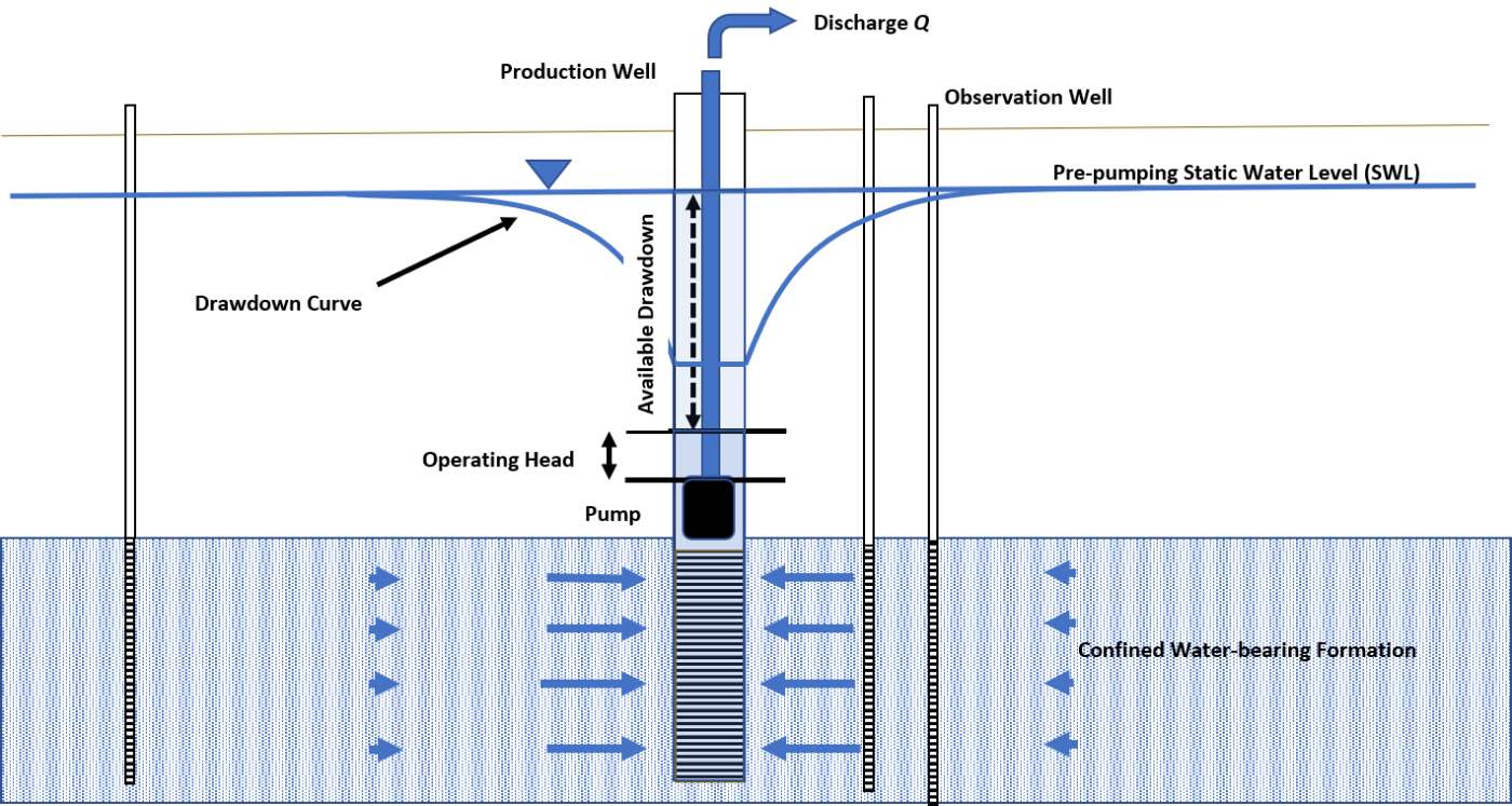
Figure 14 – Schematic of a pumping well showing the available drawdown and pump operating head. When pumping commences, available drawdown decreases. In settings with large water columns (i.e., static water level well above the pump level), the available drawdown is greater than in situations where static heads are closer to pump intake levels. Pumps require some operating head (depth of water over the pump) to generate an uninterrupted supply of water. If the water level declines below the operating water level the water will entrain air which reduces flow rates and causes cavitation in the pump. Pump operating manuals should be consulted to determine the minimum operating head when assessing the available drawdown needed to complete a test.
Operation of the selected pump also requires a reliable power source. Commonly, electrical power supplies or generators are used to operate submersible or line shaft turbine pumps. If power is interrupted during the test, it may be necessary to terminate the test and allow water levels to recover to near pre‑test levels and then start over. Brief interruptions in power that occur later in the test can be compensated for by pumping at a calculated higher rate so that the average rate remains unchanged. However, a reliable power source and pump are key components of successful pumping tests.