
15.1 The Packer Test
Hydraulic testing of isolated portions of a borehole is usually accomplished using inflatable packers to seal off the interval of interest (Figure 133). Single‑packer systems can be used to test the entire interval of borehole/well below the packer, or a double‑packer (also called straddle‑packer) system can be installed to test the zone located between the packers.
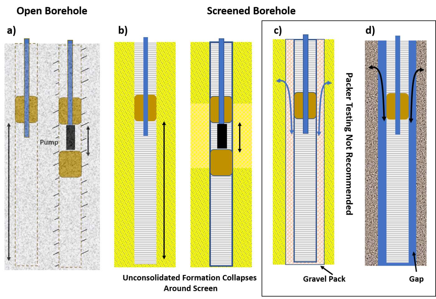
Figure 133 ‑ Packers (brown rectangles) are used to isolate a portion of a borehole or perforated zone of a well to allow characterization of the zone below (single) or in between the packers (double). Black rectangles represent pumps. a) Packer systems in an open borehole in unfractured and fractured rock (angled lines) in which slug tests, pumping tests, or injection tests can be performed. b) Packer systems in a screened borehole in which pumping, or injection tests can be performed. The formation is well connected to the screen. c) Single packer inside a well screen surrounded by a gravel pack that allows leakage of water from a portion of the borehole above the packer. Packer testing is not recommended under this condition. d) Packer in a well screen that is not seated in the formation and has a gap between the screen and formation. Packer testing is not recommended in this condition.
Packers are typically constructed of thick rubber or other flexible material and are inflated with nitrogen, compressed air, or water to form a tight seal against the borehole wall. The packers (single or double) are designed with an open‑center portion that allows for testing tools and the installation of pressure transducers (Figure 134).
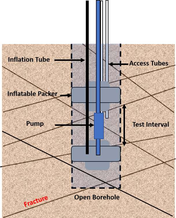
Figure 134 ‑ Schematic of inflatable packer set up in a fractured rock (angled lines) uncased (open) borehole (dashed lines). Double‑packer systems are also called straddle packers. The packer assemblage shown is suspended by a pipe (blue). The pipe can be left as an open pipe, or a pump installed in the test region (blue rectangle). The packers are inflated using an airline in this diagram (black). The assembly also includes one or more access ports (open pipes) which can be outfitted with transducers or water samplers.
Selecting the Test Interval
It is important to have a clear purpose for the packer test. A goal could be to select only the most productive zones for screening when casing a new water‑supply well, to identify the overall generalized hydrogeologic properties of the formation, or to determine the characteristics of fractures or fault zones.
The test design and test method(s) will depend upon the stated goals and the hydrogeological conceptual model of the setting. This includes the local hydrostratigraphy, groundwater‑flow directions, anticipated magnitudes of hydrogeologic properties, and a general water budget. When fractured systems are being evaluated the likely density and connectedness of secondary permeability features is also valuable information.
Site information is derived from the literature, drillers logs and investigative tools such as coring and borehole geophysical investigations. When traditional water‑well drilling methods are used to construct an open borehole, drillers’ logs and samples of the cuttings are reviewed. In addition, reviewing the driller’s notes on observed changes in water production is valuable.
In some geologic settings boreholes may be constructed by coring. This method can provide continuous samples of the geologic material that greatly aids in the selection of test zones. The drill crew can monitor changes in injection pressure at the rig control panel to estimate relative differences in permeability throughout the borehole. Depth to water measured at the beginning of each drilling shift can also be useful for estimating heads in different portions of the borehole.
In addition to observations made during well drilling, most often further investigations of the borehole are completed before a selection of a packer‑testing intervals. Once the borehole is completed, a suite of borehole geophysical tools can be deployed to identify precise locations of lithologic changes, as well as zones of higher permeability and increased fracturing. Methods include a caliper log to assess borehole diameter and condition and an acoustic televiewer log to identify fractures. Additional logs may be needed depending on the formational properties and testing purpose. Shapiro (2007) recommends that a flow‑meter log be conducted under static conditions and pumped conditions prior to determining test intervals. Detailed temperature profiles are often useful to characterize fractured systems (e.g., Pehme et al., 2014).
When selecting a test interval, it should be recognized that the borehole construction process may have altered the borehole wall creating a “skin” of lower‑permeability material that coats or plugs portions of the formation. An appropriate well‑development technique is recommended prior to testing, such as surging, jetting, or over pumping to reduce the influence of the skin (Sterrett, 2007).
Setting up the Packer System
Shapiro (2007) described the components and setup of a packer system referred to as the Multifunction Bedrock‑Aquifer Transportable Testing Tool (BAT). His publication provides a good framework for understanding how a packer system is designed and installed and is used here to describe general packer‑system installation and operation.
A packer system is set up for a given interval of the borehole. It is often attached to a rigid pipe that is lowered into the borehole or, in some settings, a cable and winch. If attached to a steel pipe, rigid‑pipe extensions are added to the testing equipment to reach deeper locations. Because of the size and weight of the equipment and the need to raise and lower it in the borehole, a service truck with a boom, winch, and cable is often required to secure the tools while the packer system is lowered, operated, and raised.
Electricity is required to operate recording devices such as electronic valves and computers. Often an electric submersible pump is placed in the test interval. An onsite generator is used when power is not available.
Additional tubing and connectors are attached to allow inflation and deflation of the packers, and to house transducers and other equipment. If water is to be injected into the test zone from the surface, a reservoir to hold the water is required.
It is recommended to follow the manufacturer’s instructions when installing, inflating, and deflating the packers. Shapiro (2007) provides further details on the setup and installation of packer equipment. Refer to inflation/deflation tables by depth and borehole size to determine the inflation pressure. Too much inflation pressure can fracture/damage the borehole wall and too little pressure can result in leakage between the packer and the borehole wall.
Shallow, small‑diameter borehole intervals are sometimes isolated using flexible packers made of closed‑cell foam attached to the outside of a rigid rod or tube. At locations with shallow wells these can be pushed into place and removed by hand. Small‑diameter inflatable packers can be constructed using available hardware or purchased commercially.